
Questions and answers

Search questions and answers about leaf specifications, use, and combinations.

Ask a question
TopicSelect multiple
Communication and interfacesSelect multiple

17questions

What voltage does the Taiyo Yuden LTE-M leaf use?

Power and voltage LTE-M AC09AV06AV01

The AC09 Cat-M1 TY leaf takes power from the 3.3V Leafony Bus pin.

It helps to distinguish the standalone module’s specifications from those of the assembled leaf when choosing a power supply.

DevicePower specification
AC09 leafSupply the 3.3V Leafony Bus pin (pin 1)
Standalone Taiyo Yuden WSCLxADAH2Z-series moduleManufacturer-specified operating range: 2.3–4.2V

The 2.3–4.2V range applies to the standalone module, rather than the Leafony Bus input. AC09 also includes power circuits for the RF and signal sections, plus UART level conversion.

For battery-powered AC09 operation, we recommend the AV06 1.8V–5.5V power leaf with an external battery such as dry cells. AV06 converts a 1.8–5.5V input to 3.3V for the leaves. The 1.8–5.5V range applies to the battery connected to AV06.

The AV01 and CR2032 coin-cell supply included in Basic Kit 2 is not suitable for LTE-M communication. Producing 3.3V and supplying enough current during transmission are separate requirements. If you add AC09 to Basic Kit 2, review the power configuration too.

The published AC09 sample also uses AV06. AV06 specifications list a maximum output current of 1A, but the current available in practice also depends on the battery and input voltage. Check the battery specifications alongside the total current required by the connected leaves. Measured AC09 peak current will be announced after verification.
References

Can I connect an external sensor?

Connections I2CGrove AX02BAX06AI05

Yes. You can choose a connection to suit the sensor’s interface and voltage.

ConnectionTypical use
AX02B 29-pinBreak out the 29 Leafony Bus signals to 2.54mm-pitch pads for wiring
AX06 Grove&5VConnect I2C, UART, analog, or digital signals using Grove connectors
J1 on AI05 Env SensorsConnect an external 3.3V I2C sensor to GND, 3.3V, SDA, and SCL

These four points help you choose a suitable combination:

  • Supply voltage and current: Can your power source supply the sensor?
  • Signal levels: Do the MCU and sensor use compatible levels? A sensor’s 5V supply requirement is separate from its signal voltage. AX02B has no voltage conversion, so add level shifting where needed.
  • Pins and I2C addresses: Are there conflicts with other leaves? For example, the AI05 accelerometer and AX06 I/O expander both use 0x18.
  • Software: Is there a driver or library for your MCU and development environment?

For Grove sensors, checking voltage and signals alongside the connector type helps you choose a compatible device. See Combining leaves and choosing power for details.

A sequence for your first test

  1. Check the sensor datasheet for its interface, supply, and signal voltage, then choose a connection from the table above. For I2C, also check the address map for conflicts with existing leaves.
  2. Disconnect all power before wiring. Start with the MCU, power source, required connection leaves, and one external sensor.
  3. Run a minimal sensor-reading example compatible with your MCU and check readings through serial output or a similar display.
  4. Once readings work, add other leaves and processing one at a time. If an I2C sensor stops responding after an addition, see I2C address and connection checks.

What sensors are available?

Choosing sensors AI01AI02AI03AI05

Choose a sensor leaf according to what you want to measure, such as temperature, humidity, light, acceleration, or pressure.

LeafStandard capabilities
AI01 4-SensorsTemperature, humidity, light, and acceleration
AI05 Env SensorsTemperature, humidity, and pressure (BME280), plus acceleration (LIS2DW12)

AI05 also has locations for optional SHT40, SGP40, and BME680 components. These are not fitted as standard, so gas or air-quality measurements need a configuration that includes the additional components.

Discontinued leaves

AI02 and AI03 are discontinued. The following information is for people who already own these leaves.

LeafStandard capabilities
AI02 SP&PIR (discontinued)Infrared sensing for detecting a person approaching; also includes a speaker
AI03 MIC&VR&LED (discontinued)Microphone input; also includes a potentiometer and LED

Approach detection depends on installation and detection range; sound measurements also depend on microphone sensitivity and processing. The microphone example is a starting point for exploring changes in sound. Using it as a calibrated sound-level meter requires consideration of accuracy and calibration as well.

For a new project that needs approach detection or microphone input, or for other measurements, you can also connect an external sensor. Your measurement target, range, frequency, and required accuracy will help narrow down the options.

Where can I buy Leafony?

Purchasing

You can buy kits and leaves from Leafony Shop.

If you are getting started, the product list helps you compare kit contents before visiting the shop product pages.

Each product page has current pricing, stock, and lead-time information. Some products with documentation may be discontinued or awaiting release.

For a standard purchase, choose products and quantities on the product pages, then proceed from the cart to checkout. To choose a configuration, check Combining leaves and choosing power and the example catalog.

If you need an individual quotation document, use the Leafony Shop contact page (Japanese).

Are the wireless leaves certified for use in Japan?

Radio certification LTE-MLoRa AC07AC08AC09

Yes. When a certified wireless module is used with an antenna covered by its certification, within the specified conditions, customers do not need additional Japanese radio certification for that same radio equipment.

About the module and antenna combination

Certification covers the module and antenna combination, along with conditions such as output power and frequency.

Leafony uses STAF onboard antennas as part of combinations covered by the corresponding module certification. For example, AC08 LTE-M Mary uses the certified combination of Murata Type 1SC and STAF 1019-085A. AC07 LoRa Mary also documents Type ABZ with the same antenna.

AC09 Cat-M1 TY uses a Taiyo Yuden module and STAF 1019-085A. Taiyo Yuden states that using an antenna covered by Japanese radio certification avoids additional certification. The module model, certification number, and corresponding antenna documentation let you check a specific configuration.

Where is the certification marking?

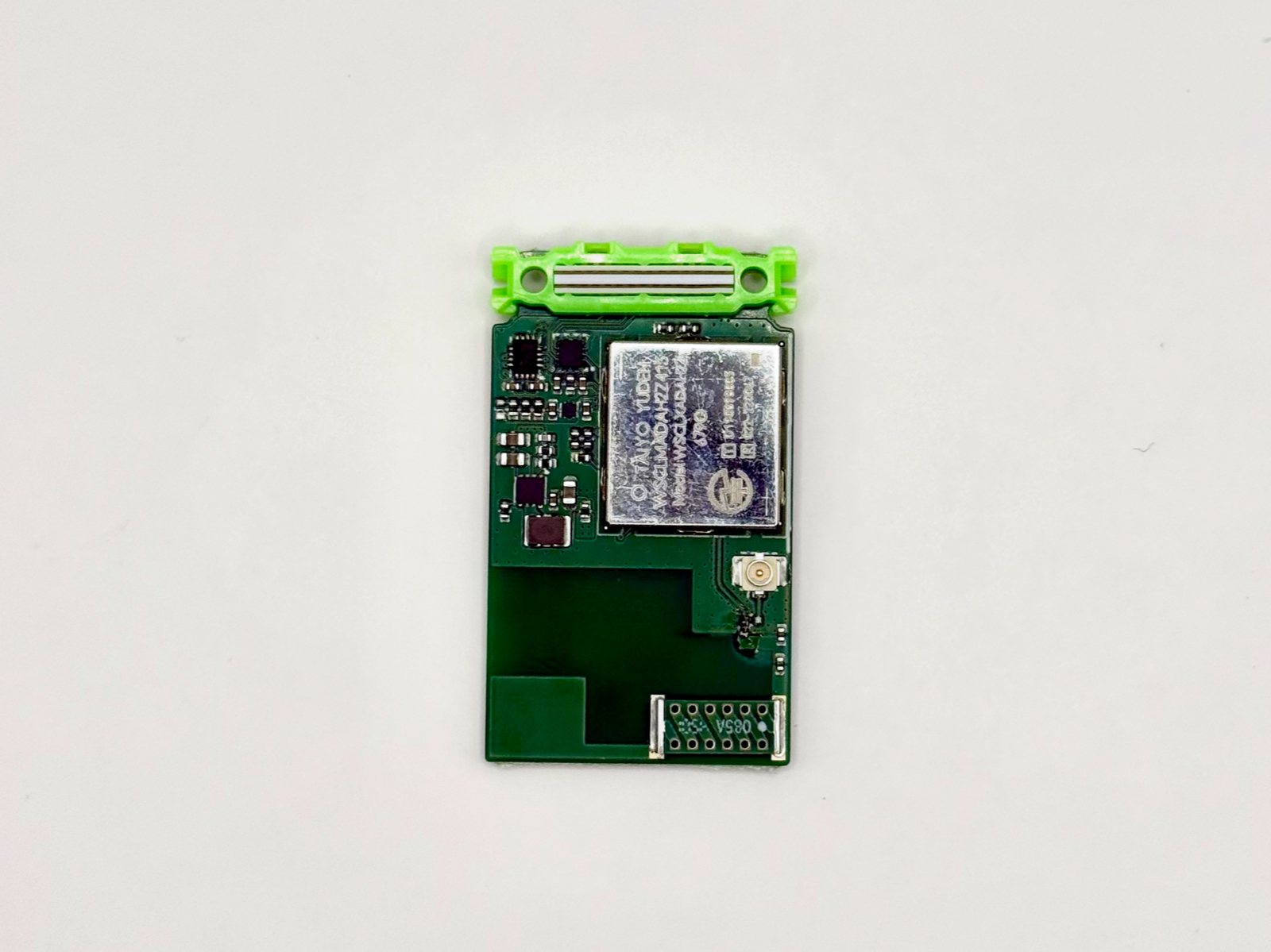
Look on the wireless module itself, mounted on the leaf. Some modules display the Japanese certification mark and number on their metal shield or other surface. “On the chip side” refers to the wireless module body here. The location and marking method vary by product; manufacturer documentation can help you find them.

AC09, showing model and certification-related markings on the metal shield of the Taiyo Yuden module.

If assembly hides the marking, disconnect all power before checking it. For small text, take a photo of the module surface with a smartphone or similar camera, zoom in, and compare it with the photos and module name in the leaf’s technical documentation. Distinguish the leaf model printed on the board from the module model and certification number printed on the module.

If you would like to change the antenna

For an external antenna or changes to the radio circuit, use the manufacturer’s certification documents to check whether the new configuration is covered. Alongside connector compatibility, the antenna model and operating conditions are the key points to check.

This explanation concerns Japan’s Radio Act. Overseas certification, cellular subscriptions, and carrier compatibility can be checked separately.

References

How should I match the STM32 Core and RTC library versions?

Programming BLE AP03

Choose compatible versions of STM32RTC and the STM32 Arduino Core supplied by your board configuration. The current Docs also explains library versions in older samples.

If an older sample produces a compatibility error such as Please update the core, compare the settings below. Check whether the Core meets the library’s requirements.

  • Arduino IDE: Check the selected package and version in Boards Manager, and the STM32RTC version in Library Manager. Distinguish the Leafony package for AP03 from the generic STM32 package.
  • PlatformIO: Check framework-arduinoststm32 in the build log and lib_deps in platformio.ini.

The current STM32RTC requirements specify library 1.x for Core 1.3.0 or later, below 3.x, and library 2.x for Core 3.x or later. Earlier 1.x releases may have different requirements, so also check the README and header for the version you use. If you use STM32LowPower, match its requirements too.

See Libraries and board definitions and PlatformIO setup for AP03 settings. Keep a copy of your original configuration and try building a small sample before returning to your program.

Historical question consulted: “leafony の STM32 Simple BLE Beacon について” by tiri-leafony-users (October 11, 2023, Japanese). The resolution of the original issue is unconfirmed. This answer summarizes version-selection guidance that remains useful today; it does not imply that the original error is still occurring.

Can a Windows C# app receive Leafony BLE data?

Programming BLE AP01AP03

Yes. If your configuration runs a BLE sample that uses GATT communication, you can build a receiver using Windows BLE APIs. Match the PC receiver to the program running on Leafony.

Start with the AVR Web Bluetooth sample or STM32 sample and its receiver code.

  1. Identify the leaves and the program running on them.
  2. Check service and characteristic UUIDs and how Read, Write, and Notify are used.
  3. Discover the service on Windows and implement the appropriate operations, such as subscribing to notifications.
  4. Interpret the received bytes using the same format as the sample.

Microsoft’s GATT client guide includes C# examples for service discovery and notifications. A device name alone does not explain its data, so also check the BLE data format.

Also check support for your Windows SDK, app type, adapter, and driver. A beacon-only sample behaves differently from connection-based GATT communication.

Historical question consulted: “leafonyの開発環境について教えてください” by ike (April 15, 2024, Japanese). Operation with the post’s combination of Windows 10, Visual Studio 2017, and a particular BLE dongle, and the resolution of that request, are unconfirmed. This answer does not recommend that older environment; it describes how to build a receiver using current official documentation.

Where can I find the BLE data format and UUIDs?

Connections BLE AP01AP03AI01

Check the transmitter and receiver code for your sample together. Leafony does not use one universal data format; it depends on the program you upload.

In the AVR Web Bluetooth sample, 4-Sensors_BLE.ino sends temperature, humidity, illuminance, tilt, battery voltage, and a dice value as comma-separated text. The receiver’s handleData() in leafony.js decodes UTF-8, removes line breaks, and splits the text at commas.

  • UUIDs and notifications: Check the service and characteristic settings in the receiver app’s source code.
  • Fields and their order: Compare the data-generation code in your MCU sketch with the receiver’s parser.
  • Beacons: Some samples use Advertising data instead of GATT notifications. See STM32 Simple BLE Beacon.

If you add fields to the transmitted data, update the receiver’s field count, order, and units as well.

Why can I discover a BLE beacon but not connect to it?

Connections BLE AP03

If you are running STM32 Simple BLE Beacon, operating without a connection is intentional. Discovering a device does not necessarily mean it accepts connections.

This sample uses LE_GAP_SCANNABLE_NON_CONNECTABLE. The receiver reads Advertising data by scanning; the published code sends the device name Leaf_A and the text HELLO BEACON.

To receive sensor values after connecting or send commands to Leafony, start with a connection-based sample such as STM32 Web Bluetooth.

Other beacon samples and custom programs may use different connection settings and data formats. First check the name of the program running on the device.

Should I start with Arduino IDE or PlatformIO?

Programming AP01AP02AP03

Start with the environment recommended by the sample you want to run. Leafony Docs includes Arduino IDE and PlatformIO instructions for AP01, AP02, and AP03.

GoalA useful starting point
Open an .ino sketch and try a small sampleArduino IDE instructions
Edit in VS Code and manage configuration files with the programPlatformIO instructions
Reproduce an existing projectThe tools and settings specified by that project

See Development environment for setup and Libraries and board definitions for board settings. Add sensor and communication libraries as specified by the sample.

AP03 and AP03B are different models. For AP03B or another MCU, check the instructions provided for that model. Using the same tool does not guarantee that board settings and pin assignments can be reused.

Why does my STM32 program not run after an “upload complete” message?

Programming UART AP03

On AP03, change the switch position between programming and running, and reset after each change. Check this sequence:

  1. Close the serial monitor and other apps using the same port.
  2. Set AP03 to Program, reset it, and upload.
  3. Check that connection, programming, and verification succeeded in the programmer’s log.
  4. Set the switch back to Run and reset again to start the program.

Arduino IDE may show a completion message while the log contains Timeout error occured while waiting for acknowledgement. In PlatformIO, check the STM32CubeProgrammer verification result as well as SUCCESS.

See the Arduino IDE instructions or PlatformIO instructions for switch locations and log examples. If only serial output is missing, check that the monitor’s port and baud rate match your program’s Serial.begin() setting.

These steps apply to AP03. For another MCU, use that model’s upload instructions.

How do I fix a “No such file or directory” build error?

Programming AP01AP02AP03AI04

Compare the filename in the error with the library specified by your sample. The required library may be missing, or a different implementation may be installed.

  • Arduino IDE: Check the name and author in Library Manager. For ZIP releases, use Sketch → Include Library → Add .ZIP Library.
  • PlatformIO: Check lib_deps in the active [env:...] section. Settings in another environment do not apply to that build.

For example, the AI04 samples use ST7032.h from tomozh’s arduino_ST7032. LCD_ST7032 and ST7032_asukiaaa are different libraries. Match the source rather than relying on a similar name.

Libraries and board definitions lists common sources and installation steps. If the build still fails after installation, start with the first error in the log and use these checks.

Message or situationWhat to check next
The same header still produces No such file or directoryCheck that the full library is installed and match its name, author, and header filename. For manual Arduino IDE installation, follow the official instructions: place the library in the sketchbook’s libraries folder and restart the IDE.
A different header is missingCheck the sample or library README for required dependencies and install them.
PlatformIO is building a different environmentMatch the active environment name to the [env:...] section containing lib_deps.
The header is found, but a Core compatibility error appearsThis is a different cause from a missing header. For STM32, check Core and RTC library compatibility.

Do I need a SIM and a mobile service plan for LTE-M?

Connections LTE-M AC09

Yes. To use the mobile network with AC09, prepare a compatible nanoSIM, an active service plan, and the required settings. Even when a product includes a SIM, check its service status and configuration.

The AC09-to-Google-Sheets sample documents SIM settings for 1NCE and SORACOM (plan-D). Match settings such as the APN to your SIM.

When choosing a SIM, check:

  • Cat-M1 service requirements and coverage in your area
  • SIM size, activation or service status, and contract terms
  • The sample’s APN settings and your MCU/communication leaf configuration

The published sample targets AP03 + AI01 + AC09. It does not verify operation with the AP03B + AI05 Cat-M1 Kit or guarantee compatibility with every SIM. Check Cat-M1 Kit development preparation and AC09 specifications for the target configuration.

Can I send measurements to Google Sheets over LTE-M?

Programming LTE-M AC09AP03AP03BAI01AI05

A reference sample for sending data to Google Sheets is available. The AC09 temperature and humidity sample describes sending AI01 readings through AC09 over HTTPS to Google Apps Script, which appends them to a sheet.

It targets AP03 + AI01 + AC09. Prepare the required hardware, including a SIM, power source, and USB interface, plus a Google account, receiver-side Apps Script, destination URL, and token settings.

Under normal conditions, the sample is designed to read a new measurement and start sending it every 10 minutes. Actual arrival intervals depend on communication conditions. Automatic time acquisition at startup with AC09 and the chosen SIM has not yet been tested on hardware, and power-saving and battery-runtime evaluations are also pending. Begin by validating your configuration.

The program cannot be uploaded unchanged to the Cat-M1 Kit’s AP03B + AI05 configuration. AI05 has different sensors, and AP03B board settings and pin connections also need checking. Kit development preparation explains the differences and the instructions still in preparation.

Why did my I2C sensor stop responding after I added a leaf?

Connections I2CGrove AI05AX06AC08AC09

Check for duplicate addresses on the same I2C bus. Devices may work individually but become impossible to address separately when another leaf uses the same address.

CombinationDuplicate address
AI05 LIS2DW12 accelerometer and AX06 I/O expander0x18
AC08 and AC09 control I/O expanders0x21

These are 7-bit addresses. Check other combinations in the I2C address map. Whether an address can be changed depends on the component and board implementation, so check each leaf’s specifications before changing only the software address.

If addresses do not overlap, also check power, signal levels, pin conflicts, and pull-up resistors. For example, AI05 R18 and R19 are not populated; with AP03, it uses the pull-ups on AP03.

Start from the configuration that worked

Disconnect all power before changing the stack, then work through these checks.

  1. Remove the added leaf and test with the original program. If the original configuration also fails, the added leaf may not be the only cause. Check power, contacts, wiring, and the program.
  2. Add leaves one at a time. When readings stop, compare the pins and I2C addresses used by that combination.
  3. If addresses overlap, first use just one of those devices. If you need both, check whether each device and board supports an address change. Changing only the software address setting does not change the actual device address.

See Combining leaves for a connection checklist.

Which programming languages can I use with STM32?

Programming AP03

You can write programs in C and C++. Leafony’s AP03 STM32 MCU is intended for development with Arduino IDE or STM32CubeIDE.

An Arduino program is called a “sketch.” A sketch in an .ino file is compiled as a C++-based program. Knowledge of variables, conditions, loops, and functions learned in C is useful here too.

  • setup(): Runs once at startup. Use it to initialize sensors, communication, and other settings.
  • loop(): Runs repeatedly afterward. Use it for tasks such as reading sensors and sending data.

If you are new to this, set up the development environment and libraries and board definitions, then choose an STM32 example from the sample catalog. Start by changing small parts of its values or behavior.

ST’s STM32CubeIDE supports C/C++ development and debugging with a debugger. See connecting a debugger for the AP03 connection setup. An Arduino sketch cannot simply be opened as a CubeIDE project, so start with the environment specified by a Leafony Arduino sample when trying that sample.

Reference: Arduino’s sketch build process

Can I use Python with Leafony?

Programming BLEUART AP01AP02AP03

On-leaf development is intended to use C/C++ with Arduino IDE, or STM32CubeIDE for STM32 leaves.

For Arduino samples, see the development environment. To use STM32CubeIDE and a debugger with AP03, see connecting a debugger. Arduino sketches and CubeIDE projects use different settings and library integration, so they may require changes when moving between environments.

Python can run on a PC to receive Leafony data, save it, plot it, and analyze it. Write a Python receiver that matches the data sent by the C/C++ program on Leafony.

ConnectionPython options and things to check
Serial communication over USBReceive data with pySerial. Upload a program that outputs serial data, then match the port, baud rate, and data format, including line endings. The leaf needed for USB connectivity depends on the MCU.
BLE wireless communicationUse Bleak to read GATT characteristics or receive notifications. Check the PC’s Bluetooth environment and the sample’s connection method, UUIDs, and data format.

For USB, the STM32 temperature and humidity sample provides an example of serial output. Its baud rate is 115200 bps. First check that values appear in Arduino IDE’s serial monitor, then close the monitor before opening the same port from Python.

For BLE, use the data format and UUID guidance to write a receiver that matches your sample. For a non-connectable beacon, scan its advertising data instead of making a GATT connection.

To run Python on the leaf itself, you need a separate runtime such as MicroPython. MicroPython for ESP32 is available, but a supported chip alone does not mean that every Leafony leaf or sensor will work unchanged. Check the firmware for the board, pin configuration, and sensor drivers. Leafony Docs currently does not include hardware-verified MicroPython setup instructions for AP02 or AP03.

If your goal is sensor data analysis, start with an existing Arduino sample on Leafony and Python on the PC. Also see programming languages for STM32.

When adding a leaf, use the combination guide to check the MCU, power supply, pins, and I²C addresses.

Search documentation, sample apps, and Q&A