
Measure Current and Reduce Power Consumption
Explore with your favorite AI
 ChatGPT
  Claude
 Gemini & other AI
Copy this page’s context into your AI to explore how it works and what you can build.
 Open Gemini
 Copy the prompt, then paste it into Gemini’s message box.
View prompt
Estimating battery life and reducing power consumption requires current measurements over time, including sleep, rather than just active peaks. This guide explains how to measure current on the leaf side with AX05B I Meas and compare changes under the same conditions.
For calculation methods, see Low-Power Design and Battery Runtime. This is a measurement guide; it does not report measured current or battery life for a particular configuration.
1. Decide What to Measure
Section titled “1. Decide What to Measure”| Question | Measurement location | What it includes |
|---|---|---|
| Effect of changing MCU or sensor settings | AX05B V33 line, with the target above and the power source below | Current through the instrument to the upper leaves on the 3.3V line |
| Current drawn by circuits using VBUS | AX05B VBUS line | Current through the instrument on the VBUS line |
| Total consumption seen by the battery | Between the battery and power leaf | Battery-side current, including power conversion losses |
Current on the 3.3V line is not the same as battery current. It also excludes circuits below AX05B and any unmeasured power paths. Evaluating battery runtime requires a battery-side measurement or a calculation that accounts for power conversion.
2. Check Power Paths and Instrument Mode
Section titled “2. Check Power Paths and Instrument Mode”The following current path applies when measuring V33 supplied by a power leaf through AX05B. Disconnect all power before changing wiring.
Battery → power leaf (below AX05B) → AX05B V33IN → current meter → AX05B V33OUT → MCU, sensor, and communication leaves under test (above AX05B)Nordic Power Profiler Kit II (PPK2) has an Ampere Meter mode for measuring an external supply and a Source Meter (SMU) mode in which the instrument supplies power. The power source and wiring differ between these modes. See the manufacturer’s power supply and mode documentation.
| Mode | Power source | Use in this guide |
|---|---|---|
| Ampere Meter | An external source, such as a battery and power leaf | Insert the current meter in series in the path above |
| Source Meter (SMU) | PPK2 | A different configuration. Define the output voltage and load, disconnect other paths supplying that load, and follow the manufacturer’s connection procedure |
The remaining steps use Ampere Meter mode. Do not switch modes while retaining the same connected wiring.
3. Connect the Current Meter to AX05B
Section titled “3. Connect the Current Meter to AX05B”For soldering, pin numbers, and connection photos, see the AX05B measurement procedure.
| PPK2 | AX05B J1 (V33) |
|---|---|
| VIN | V33IN (pin 3) |
| VOUT | V33OUT (pin 2) |
| GND | GND (pin 1 or 4) |
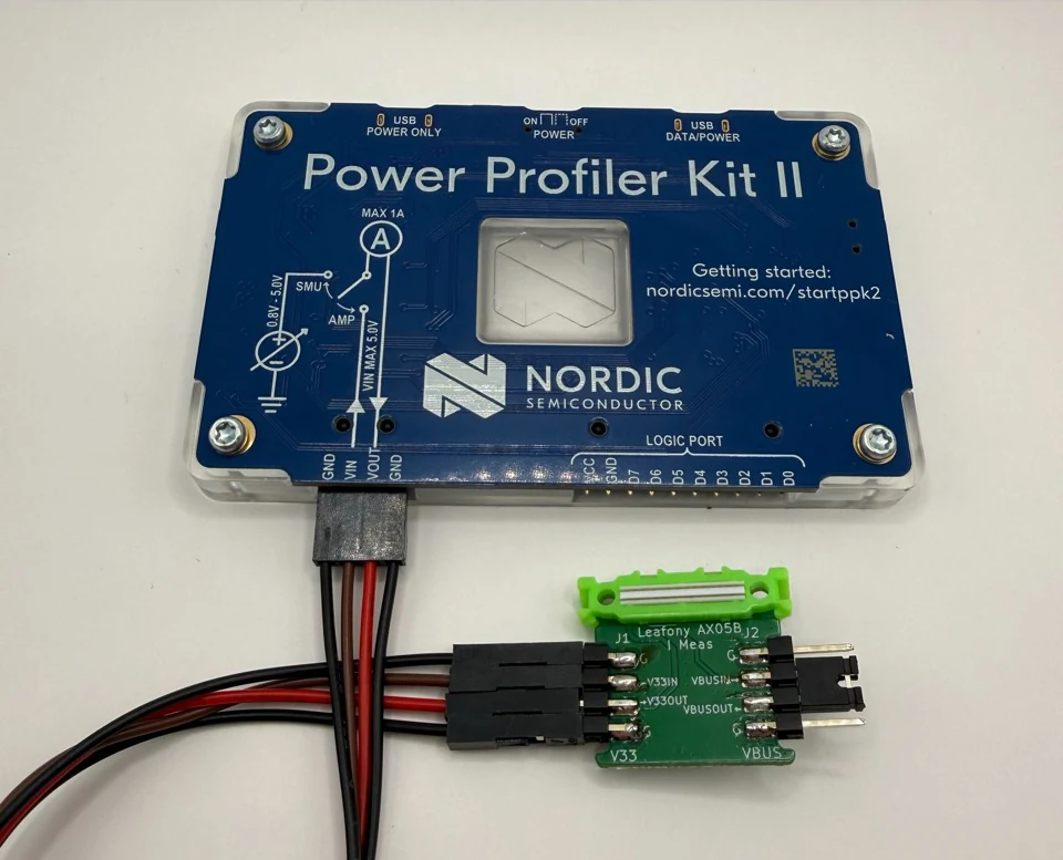
- Route the measured V33 line through the current meter between IN and OUT. A parallel jumper would bypass the instrument.
- For the unmeasured VBUS line, connect IN to OUT with a jumper as described in the AX05B procedure. However, if VBUS supplies power to the target, V33 current alone does not represent its total current.
- A power source such as a USB leaf above AX05B may create a path that bypasses the current meter. When measuring battery operation, remove unneeded supplies such as the Leafony USB connection. Distinguish this from the USB connection that powers PPK2 itself.
- Check that voltage and current are within the instrument’s input limits, and confirm that inserting the meter does not cause resets or communication failures.
Also see the manufacturer’s connector descriptions and Ampere Meter procedure.
4. Record a Complete Active and Sleep Cycle
Section titled “4. Record a Complete Active and Sleep Cycle”- Record leaf models, revisions, stacking order, firmware version, instrument, supply voltage, measurement date, and temperature.
- Record startup and network connection activity after power-on. Keeping initial startup separate from steady operation makes comparisons clearer.
- During steady operation, record wake → sensor reading → transmission → sleep → next wake. Do not calculate an average using only low-current periods.
- Confirm that sensing and communication succeed using logs or received data. If retries or other events change the cycle length, record multiple cycles.
- Save the comparison interval duration, average current, peak current, and trace.
5. Compare Averages over the Same Interval
Section titled “5. Compare Averages over the Same Interval”If current can be treated as constant within each state, calculate the time-weighted average below. If it varies, use the average of the full interval recorded by the instrument.
Average current = Σ(current in each state × time in that state) / total recorded timeIf voltage changes, average voltage multiplied by current over time to obtain average power. Do not directly compare 3.3V-side and battery-side currents; use the same measurement location and supply conditions.
| Condition | Comparison interval | Average current | Peak current | Sensing and transmission successful? |
|---|---|---|---|---|
| Before change | Fill in after measurement | Fill in after measurement | Fill in after measurement | Fill in after checking |
| After change | Fill in after measurement | Fill in after measurement | Fill in after measurement | Fill in after checking |
6. Change One Setting at a Time
Section titled “6. Change One Setting at a Time”Change just one setting, such as the measurement interval, radio transmission interval, unused sensor sleep mode, or MCU clock frequency. Refer to the energy reduction techniques and repeat the measurement at the same location, voltage, and comparison interval.
A lower average current, while retaining the required measurement frequency, successful communication, and responsiveness, demonstrates an improvement under those conditions. Verify final battery runtime by operating the device with the intended battery, temperature, and communication conditions.