
Camera (AVR)
Explore with your favorite AI
 ChatGPT
  Claude
 Gemini & other AI
Copy this page’s context into your AI to explore how it works and what you can build.
 Open Gemini
 Copy the prompt, then paste it into Gemini’s message box.
View prompt
Overview
Section titled “Overview”An example of using Seeed Studio’s Grove series sensors. Let’s try to save an image taken by the camera once a minute to a microSD card.
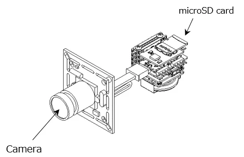
Leaf to use
Section titled “Leaf to use”| Type | Name | Q’ty |
|---|---|---|
| AZ62 | Connector Cover | 1 |
| AZ02 | RTCµSD | 1 |
| AX04 | Spacer | 1 |
| AX06 | Grove&5V | 1 |
| AP01 | AVR MCU | 1 |
| AZ01 | USB | 1 |
| AV01 | CR2032 | 1 |
| CR2032 coin cell battery | 1 | |
| Grove-Serial Camera Kit | 1 | |
| microSD card | 1 | |
| M2*18mm screw | 2 |
Assembly
Section titled “Assembly”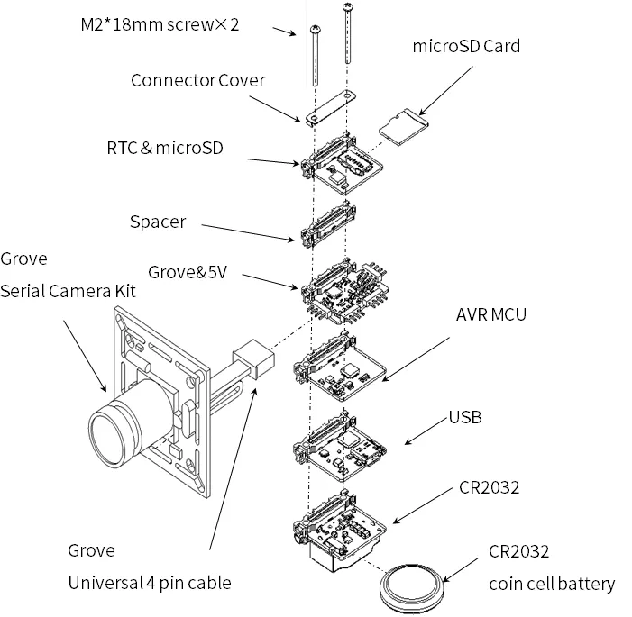
Source code
Section titled “Source code”- 4-Sensors and AVR MCU library (timer interrupt) are required for writing. Please include the library beforehand. For details, see here.
- Write the following program in the Arduino IDE.
//=====================================================================//  Leafony Platform sample sketch//     Platform     : Grove + Camera//     Processor    : ATmega328P (3.3V /8MHz)//     Application  : Camera////     Leaf configuration//       (1) AP01 AVR MCU//       (2) AX01 Grove&5V + Grove Serial Camera Kit//       (3) AZ01 USB//       (4) AZ02 RTC&MicroSD////    (c) 2019  Trillion-Node Study Group//    Released under the MIT license//    https://opensource.org/licenses/MIT////      Rev.00 2019/08/01 First release//=====================================================================//use libraries//=====================================================================
//=====================================================================// difinition//=====================================================================#include <MsTimer2.h>#include <SPI.h>#include <SD.h>#include <SoftwareSerial.h>#include <avr/wdt.h>#include <avr/sleep.h>#include <avr/power.h>//=====================================================================
#define DEBUG
//=====================================================================// SPI CLOCK// SDカードのSPI I/Fのクロック速度4Mでは動作しないので4M以下に設定すること//=====================================================================#define SD_CLCK 2500000
//=====================================================================// 撮影間隔(秒)////=====================================================================#define SNAP_WAIT 60
//=====================================================================// IOピンの名前定義// 接続するリーフに合わせて定義する//=====================================================================// --------------------------------------------// PD port//     digital 0: PD0 = PCRX    (HW UART)//     digital 1: PD1 = PCTX    (HW UART)//     digital 2: PD2 = INT0#//     digital 3: PD3 = INT1#//     digital 4: PD4 = RSV//     digital 5: PD5 = RSV//     digital 6: PD6 = RSV//     digital 7: PD7 = RSV// --------------------------------------------#define PCTX    0#define PCRX    1#define INT0    2#define INT1    3#define RSV_D4  4#define RSV_D5  5#define SD_EN   6#define RSV_D7  7
// --------------------------------------------// PB port//     digital 8: PB0 = UART2_RX (software UART)  /* not use *///     digital 9: PB1 = UART2_TX (software UART)  /* not use *///     digital 10:PB2 = CS#//     digital 11:PB3 = MOSI//     digital 12:PB4 = MISO//     digital 13:PB5 = SCK (AVR LED)//                PB6 = XTAL1//                PB7 = XTAL2//---------------------------------------------#define UART2_RX   8#define UART2_TX   9#define SD_CS     10#define MOSI      11#define MISO      12#define LED_PIN   13
// --------------------------------------------// PC port//     digital 14/ Analog0: PC0 = RSV//     digital 15/ Analog1: PC1 = CAMERA TX (software UART)//     digital 16/ Analog2: PC2 = CAMERA RX (software UART)//     digital 17/ Analog3: PC3 = RSV//     digital 18/ SDA    : PC4 = SDA   (I2C)//     digital 19/ SCL    : PC5 = SCL   (I2C)//     RESET              : PC6 = RESET#//-----------------------------------------------#define RSV_D14   14#define UART3_TX  15#define UART3_RX  16#define RSV_D17   17#define SDA       18#define SCL       19//=====================================================================
//=====================================================================// camera//=====================================================================//Color Setting#define COLOR_2BIT_GRAY   0x01#define COLOR_4BIT_GRAY   0x02#define COLOR_8BIT_GRAY   0x03#define COLOR_2BIT_COLOR  0x05#define COLOR_4BIT_COLOR  0x06#define COLOR_JPEG        0x07//Preview Resolution#define PRE_RES_80_60     0x01#define PRE_RES_160_120   0x03//JPEG Resolution#define JPEG_RES_80_60    0x01#define JPEG_RES_QQVGA    0x03#define JPEG_RES_QVGA     0x05#define JPEG_RES_VGA      0x07//Get Setting#define GET_SNAPCHOT      0x01#define GET_PRE_PIC       0x02#define GET_PRE_JPEG      0x03//Snapshot Setting#define COMPRESSED        0x00#define UNCOMPRESSED      0x01//data length#define PIC_PKT_LEN       128
//=====================================================================// SD//=====================================================================File myFile;SoftwareSerial CameraSerial(UART3_RX, UART3_TX);
//=====================================================================// 変数定義//=====================================================================unsigned long picTotalLen = 0;            // picture lengthint picNameNum = 0;char fname[16];
//---------------------------// interval Timer2 interrupt//---------------------------volatile bool bInterval = false;volatile int intcnt = 0;
//=====================================================================// setup//=====================================================================//-----------------------------------------------// port//-----------------------------------------------//=====================================================================// IOピンの入出力設定// 接続するリーフに合わせて設定する//=====================================================================void setupPort(){
  //---------------------  // PD port  //---------------------  // PD0 : digital 0 = RX  // PD1 : digital 1 = TX
  pinMode(INT0, INPUT);       // PD2 : digital 2 = INT0#  pinMode(INT1, INPUT);       // PD3 : digital 3 = INT1#
  pinMode(RSV_D4, OUTPUT);       // PD4 : digital 4 = LED  digitalWrite(RSV_D4, LOW);
  pinMode(RSV_D5, OUTPUT);     // PD5 : digital 5 = not used  digitalWrite(RSV_D5, LOW);
  pinMode(SD_EN, OUTPUT);      // PD6 : digital 6 = BLE reset active-low  digitalWrite(SD_EN, HIGH);
  pinMode(RSV_D7, OUTPUT);       // PD7 : digital 7 = BLE sleep  digitalWrite(RSV_D7, HIGH);
  //---------------------  // PB port  //---------------------  pinMode(UART2_RX, OUTPUT);      // PB0 : digital 8 = software UART2  digitalWrite(UART2_RX, LOW);
  pinMode(UART2_TX, OUTPUT);      // PB1 : digital 9 = software UART2  digitalWrite(UART2_TX, LOW);
  //---------------------  // PC port  //---------------------  pinMode(RSV_D14, OUTPUT);     // PC0 : digital 14 = not used  digitalWrite(RSV_D14, LOW);
  // PC1 : digital 15 = Camera RX  // PC2 : digital 16 = Camera TX
  pinMode(RSV_D17, OUTPUT);     // PC3 : digital 17  = not used  digitalWrite(RSV_D17, LOW);
  // PC4 : digital 18 = I2C SDA  // PC5 : digital 19 = I2C SCL}//=====================================================================// 割り込み処理////=====================================================================//-----------------------------------------------// timer2 interrupt (interval=1000ms, int=overflow)// メインループのタイマー割り込み設定//-----------------------------------------------void setupTC2Int(){
  MsTimer2::set(1000, intTimer2);}
//----------------------------------------------// Timer2 INT// タイマー割り込み関数//----------------------------------------------void intTimer2(){  intcnt++;  if (intcnt > SNAP_WAIT)  {    intcnt = 0;    bInterval = true;  }}//====================================================================// camera//====================================================================//----------------------------------------------//  clearReadBuf//  カメラデータの受信バッファクリア//----------------------------------------------void clearReadBuf(){  while (CameraSerial.available())  {    CameraSerial.read();  }}//----------------------------------------------//  sendCmd//  カメラへのコマンド送信//----------------------------------------------void sendCmd(char cmd[], int cmd_len){  for (char i = 0; i < cmd_len; i++) CameraSerial.write(cmd[i]);}//----------------------------------------------//  readRespons//  カメラからのデータ受信//----------------------------------------------int readRespons(char *dest, int len, unsigned int timeout){  int read_len = 0;  unsigned long t = millis();
  while (read_len < len)  {    while (CameraSerial.available()<1)    {      if ((millis() - t) > timeout)      {        //Serial.println("timeout");        return read_len;      }    }    *(dest+read_len) = CameraSerial.read();#ifdef DEBUG    //Serial.write(*(dest+read_len),);     //debug#endif    read_len++;  }  return read_len;}//----------------------------------------------//  initialize//  カメラとの通信確立//----------------------------------------------void initialize(){  char cmd[] = {0xaa,0x0d,0x00,0x00,0x00,0x00} ;  unsigned char resp[6];
  Serial.print("initializing camera...");
  while (1)  {    sendCmd(cmd,6);    if (readRespons((char *)resp, 6,1000) != 6)    {      Serial.print(".");      continue;    }    if (resp[0] == 0xaa && resp[1] == 0x0e && resp[2] == 0x0d && resp[4] == 0 && resp[5] == 0)    {      if (readRespons((char *)resp, 6, 500) != 6) continue;      if (resp[0] == 0xaa && resp[1] == 0x0d  && resp[2] == 0 && resp[3] == 0 && resp[4] == 0 && resp[5] == 0) break;    }  }  cmd[1] = 0x0e;  cmd[2] = 0x0d;  sendCmd(cmd, 6);  Serial.println(" done.\r\n");}//----------------------------------------------//  preCapture//  カメラの初期設定//----------------------------------------------void preCapture(){  char cmd[] = { 0xaa, 0x01, 0x00, COLOR_JPEG, PRE_RES_80_60, JPEG_RES_VGA };  unsigned char resp[6];
  while (1)  {    clearReadBuf();    sendCmd(cmd, 6);    if (readRespons((char *)resp, 6, 100) != 6) continue;    if (resp[0] == 0xaa && resp[1] == 0x0e && resp[2] == 0x01 && resp[4] == 0 && resp[5] == 0) break;  }}

//----------------------------------------------//  Capture//  カメラの撮影実施//----------------------------------------------void Capture(){  char cmd[] = { 0xaa, 0x06 , 0x08, PIC_PKT_LEN & 0xff, (PIC_PKT_LEN>>8) & 0xff ,0};  unsigned char resp[6];
  while (1)  {    clearReadBuf();    sendCmd(cmd, 6);    if (readRespons((char *)resp, 6, 100) != 6) continue;    if (resp[0] == 0xaa && resp[1] == 0x0e && resp[2] == 0x06 && resp[4] == 0 && resp[5] == 0) break;  }  cmd[1] = 0x05;  cmd[2] = 0;  cmd[3] = 0;  cmd[4] = 0;  cmd[5] = 0;  while (1)  {    clearReadBuf();    sendCmd(cmd, 6);    if (readRespons((char *)resp, 6, 100) != 6) continue;    if (resp[0] == 0xaa && resp[1] == 0x0e && resp[2] == 0x05 && resp[4] == 0 && resp[5] == 0) break;  }  cmd[1] = 0x04;  cmd[2] = GET_SNAPCHOT;  while (1)  {    clearReadBuf();    sendCmd(cmd, 6);    if (readRespons((char *)resp, 6, 100) != 6) continue;    if (resp[0] == 0xaa && resp[1] == 0x0e  && resp[2] == 0x04 && resp[4] == 0 && resp[5] == 0)    {      if (readRespons((char *)resp, 6, 1000) != 6)      {        continue;      }      if (resp[0] == 0xaa && resp[1] == 0x0a && resp[2] == 0x01)      {        picTotalLen = (resp[3]) | (resp[4] << 8) | (resp[5] << 16);        //Serial.print("picTotalLen:");        //Serial.println(picTotalLen);        break;      }    }  }
}
//----------------------------------------------//  GetData//  カメラからデータを取得しSDに書き込む//----------------------------------------------void GetData(){  char cmd[] = { 0xaa, 0x0e , 0x00, 0x00, 0x00, 0x00 };  unsigned char pkt[PIC_PKT_LEN];  unsigned int pktCnt = (picTotalLen) / (PIC_PKT_LEN - 6);
  if ((picTotalLen % (PIC_PKT_LEN-6)) != 0) pktCnt += 1;
  set_filename();  if (SD.exists(fname))  {    SD.remove(fname);  }  myFile = SD.open(fname, FILE_WRITE);  if(!myFile){   Serial.println("myFile open fail...");  }  else{     Serial.print("Saving ");Serial.print(fname); Serial.print("..... ");    for (unsigned int i = 0; i < pktCnt; i++)    {      cmd[4] = i & 0xff;      cmd[5] = (i >> 8) & 0xff;
      int retry_cnt = 0;    retry:      delay(10);      clearReadBuf();      sendCmd(cmd, 6);      uint16_t cnt = readRespons((char *)pkt, PIC_PKT_LEN, 200);
      unsigned char sum = 0;      for (int y = 0; y < cnt - 2; y++)      {        sum += pkt[y];      }      if (sum != pkt[cnt-2])      {        if (++retry_cnt < 100) goto retry;        else break;      }
      myFile.write((const uint8_t *)&pkt[4], cnt-6);      //if (cnt != PIC_PKT_LEN) break;    }    cmd[4] = 0xf0;    cmd[5] = 0xf0;    sendCmd(cmd, 6);  }  myFile.close();  Serial.println("end!!");}
//----------------------------------------------//  set_filename//  SDに書き込みファイ名を作成IMGxxxx.JPG//----------------------------------------------void set_filename(){  sprintf(fname, "IMG%04d.JPG", picNameNum);  picNameNum ++;  if( picNameNum > 100 ){    picNameNum = 0; // Overwrite  }}//====================================================================// setup//====================================================================void setup() {  //WDT disable  wdt_disable();
  //内部の各モジュールの電源OFF  //power_all_disable();  //power_timer0_enable();  //power_timer2_enable();  //power_spi_enable();  //power_usart0_enable();
  delay(10);
  Serial.begin(115200);  CameraSerial.begin(9600);

 #ifdef DEBUG    Serial.println("=========================================");    Serial.println("setup start"); #endif
  setupPort();  delay(10);  setupTC2Int();
   if (!SD.begin(SD_CLCK,SD_CS)) {    Serial.print("sd init failed");    return;  }   Serial.print("sd init finish\r\n");   initialize();   delay(1);   preCapture();  delay(1000);  Capture();  GetData();  MsTimer2::start();


}//====================================================================// loop//====================================================================void loop() {
  if (bInterval == true)  {    bInterval = false;    Capture();    GetData();  }}