
AC07 LoRa Mary
Explore with your favorite AI
 ChatGPT
  Claude
 Gemini & other AI
Copy this page’s context into your AI to explore how it works and what you can build.
 Open Gemini
 Copy the prompt, then paste it into Gemini’s message box.
View prompt
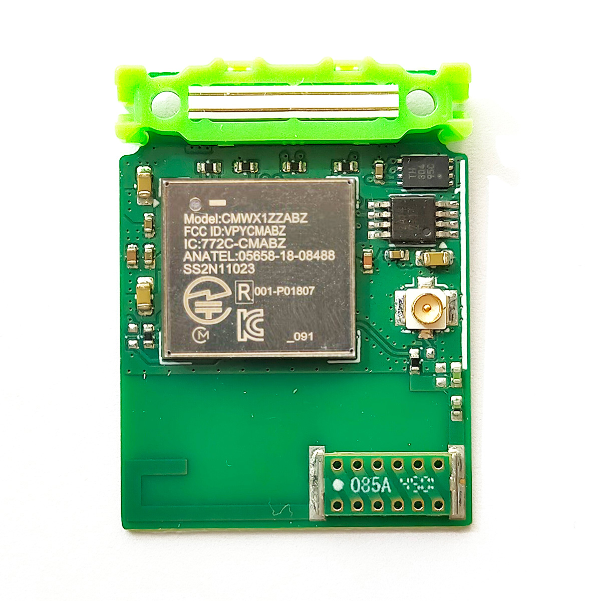
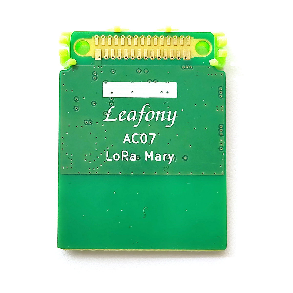
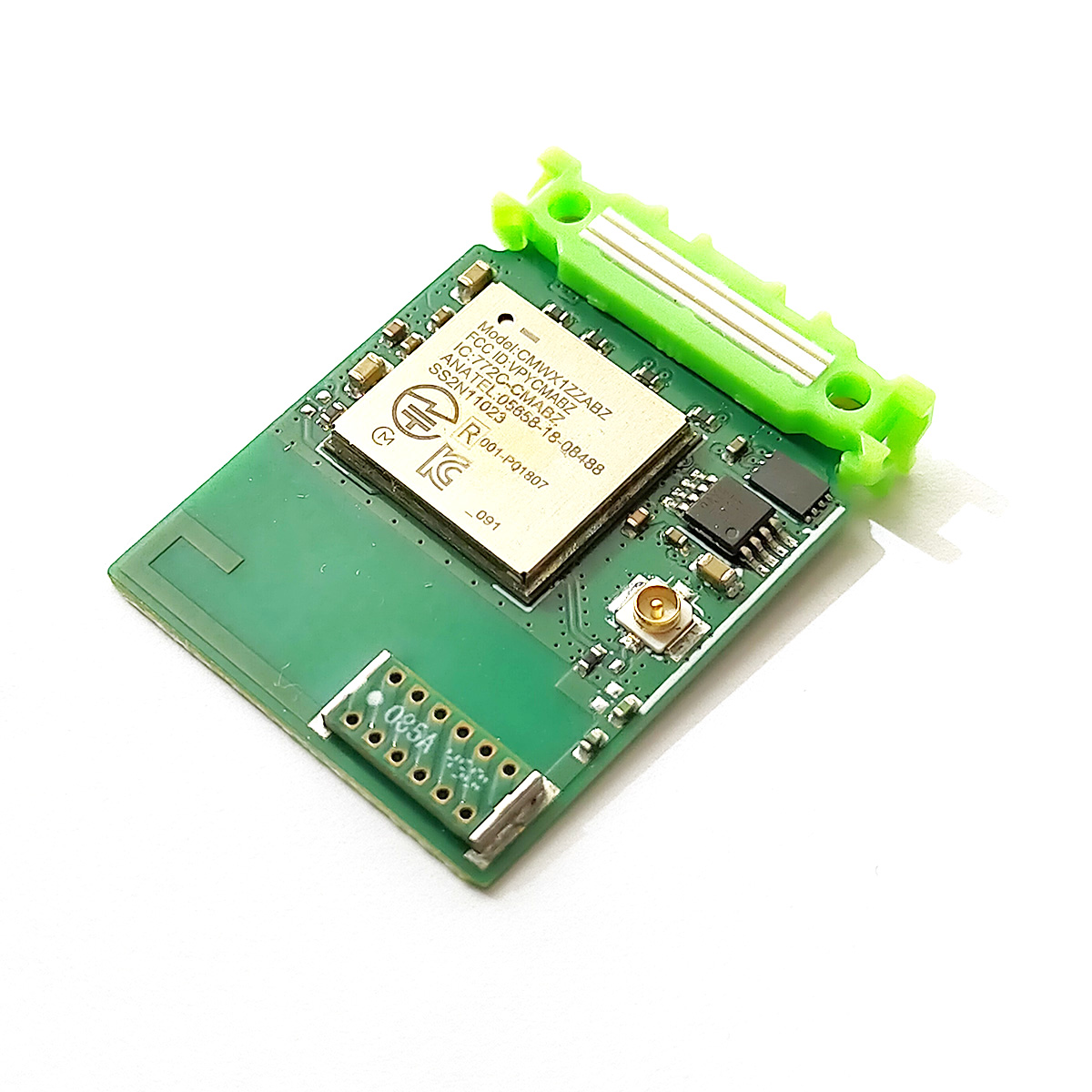
Features
Section titled “Features”Send and receive messages or sensor data over LoRa radio when combined with an MCU (microcontroller) leaf. Prepare a compatible device at the other end of the link for low-power wireless communication.
This LoRa leaf uses a Murata Type ABZ module and a chip antenna (STAF 1019-085A) with Japanese radio equipment construction design certification. It comes programmed with firmware v1.2.3, published for the Arduino MKR WAN 1300/1310, so you can program it with Arduino.
Specifications
Section titled “Specifications”| Item | Description |
|---|---|
| Part number | CMWX1ZZABZ-091 |
| Chipset | SX1276, STM32L072CZ |
| Secure element | ATECC608A |
| Carrier frequency | 920MHz band (920.6 MHz to 928 MHz), Japan |
| Modulation method | LoRa™ modulation |
| Antenna | Murata antenna support (Japanese) |
| Interface | SPI |
| RF certification | FCC, IC, TELEC, KCC |
| Dimensions | W23 × D30 × H2mm |
LoRaWAN and private LoRa
Section titled “LoRaWAN and private LoRa”LoRaWAN and private LoRa both use LoRa modulation for wireless communication, but their upper MAC layers differ. LoRaWAN is a standard developed by the LoRa Alliance that supports interoperability between devices from different manufacturers and wide-area communication. Private LoRa uses a proprietary MAC-layer protocol and requires a dedicated gateway, with no communication fees. See the following references for more information.
Board layout
Section titled “Board layout”
The Molex 73412-0110 is compatible with the U.FL RF coaxial connector developed by Hirose Electric.
Antennas
Section titled “Antennas”LoRa Mary has a chip antenna (1019-085A) with Japanese radio equipment construction design certification. For longer-range communication, attach an external antenna.1 The antennas below have this certification. See Murata antenna support (Japanese) for details.
| Model | Supplier | Antenna type | Connector | Dimensions | Note |
|---|---|---|---|---|---|
| 1019-085A2 | STAF Corporation | Monopole (λ/4) | 4 × 9.1 × 1.2mm | Chip antenna | |
| 1018-504B2 | STAF Corporation | Dipole (λ/2) | U.FL | 100 × 13 mm (cable length 140mm) | FPC antenna |
| 1019-008A | STAF Corporation | Monopole (λ/2) | SMA3 | Length 160mm, diameter 9mm | External antenna |
Pin assignment
Section titled “Pin assignment”
See the Leafony pin assignment documents for the source data.
Libraries
Section titled “Libraries”For details, see Installing Libraries.
Sample applications
Section titled “Sample applications”These samples use the STM32 MCU and LoRa Mary leaves. Include the LoRaLeafony.h library when using them.
Documents
Section titled “Documents”Programming firmware with STLINK and STM32CubeProgrammer
Section titled “Programming firmware with STLINK and STM32CubeProgrammer”- Prepare the following:
- LoRa Mary, Shield and screws
- A 3.3V power supply, or USB for power
- STLINK-V3SET
- A computer and USB cable
- Secure LoRa Mary and USB (for power) to the Shield with screws, then connect the STLINK-V3SET. See Connecting the debugger for details.
- Start STM32CubeProgrammer.
- Select
ST-Linkas the connection on the right, setFrequency(KHz)to8000, and clickConnect. - Open the erase and programming panel on the left and configure the following:
- File path: select the v1.2.3
.binfile. - Enable programming verification.
- File path: select the v1.2.3
- Click
Start Programming. Programming is complete whenDownload verified successfullyappears.
Programming firmware with FP-10 and C-Flash
Section titled “Programming firmware with FP-10 and C-Flash”- Prepare the following:
- LoRa Mary, Shield and screws
- A 3.3V power supply, or USB for power
- computex FP-10
- A computer and USB cable
- Download C-Flash:
- Enter the
CODEandSERIAL NOprinted on the FP-10 at the C-Flash download page, then download the software.4
- Enter the
- Load the program into the FP-10:
- Connect the FP-10 to the computer and start C-Flash.
- Click
設定(Settings) →ターゲット設定(Target settings). - Select the manufacturer to narrow down the microcontroller list, choose the
STM32L07xxZfilter, and click起動する(Start). - On the initial settings tab, set the target to
未接続(Not connected), and selectSWDand1MHzfor the interface. - Click
ファイル(File) →ロード(Load) →追加(Add), then select the v1.2.3.binfile. - Set the load address to
0x08000000, which is the Flash start address. - Select
データ(Data) →書き込み(Write) to load the program into the FP-10.
- Program LoRa Mary:
- Connect the FP-10 to a USB AC adapter.
- Secure LoRa Mary and USB to the Shield with screws, then connect to an AC adapter.
- Connect the FP-10 to the Shield’s SWD interface.
- Press the FP-10
PROGRAMbutton. TheSTSLED lights when programming succeeds.
Spreading factor (SF) and bandwidth (BW)
Section titled “Spreading factor (SF) and bandwidth (BW)”SF describes how much the transmitted data is spread. The LoRa library accepts values from 6 to 12, with SF7 as the default. SF6 requires implicit header mode for both transmission and reception. See the LoRa library API for details. The main characteristics are shown below.
| SF | Characteristics |
|---|---|
| SF6–SF8 | Shorter communication range and higher data rate |
| SF10–SF12 | Longer communication range and lower data rate |
BW is the width of the frequency band. Common values are 125kHz, 250kHz and 500kHz, with 125kHz as the default. The main characteristics are shown below.
| Bandwidth | Characteristics |
|---|---|
| Narrow (125kHz) | Lower data rate, longer communication range and lower power consumption |
| Wide (500kHz) | Higher data rate, shorter communication range and higher power consumption |
Footnotes
Section titled “Footnotes”-
The chip antenna and external antenna cannot be used together. To use an external antenna, reposition the 0Ω resistor. ↩
-
These antennas are certified even though they are not included in Murata’s recommended antenna list. ↩ ↩2
-
SMA stands for SUB-MINIATURE TYPE A and is a MIL-standard connector. Use a U.FL-to-SMA adapter cable to connect it to LoRa Mary. ↩
-
See the setup video (Japanese) for download and licensing instructions. ↩