
Assembling and Replacing Leaves
Set up with your favorite AI
 ChatGPT
  Claude
 Gemini & other AI
Copy the setup prompt into your AI. Work through each step together, from checking your kit to getting it running.
 Open Gemini
 Copy the prompt, then paste it into Gemini’s message box.
View prompt
Use these common steps when adding a leaf or replacing an MCU. Follow the leaf selection and stacking order in the kit or example you are using. Before changing the functional configuration, read Combining Leaves and Choosing a Power Supply to check power and pin requirements.
What You Need
Section titled “What You Need”| Part or document | What to check |
|---|---|
| Leaves to use | Model, revision, front/back orientation, and whether they match the example |
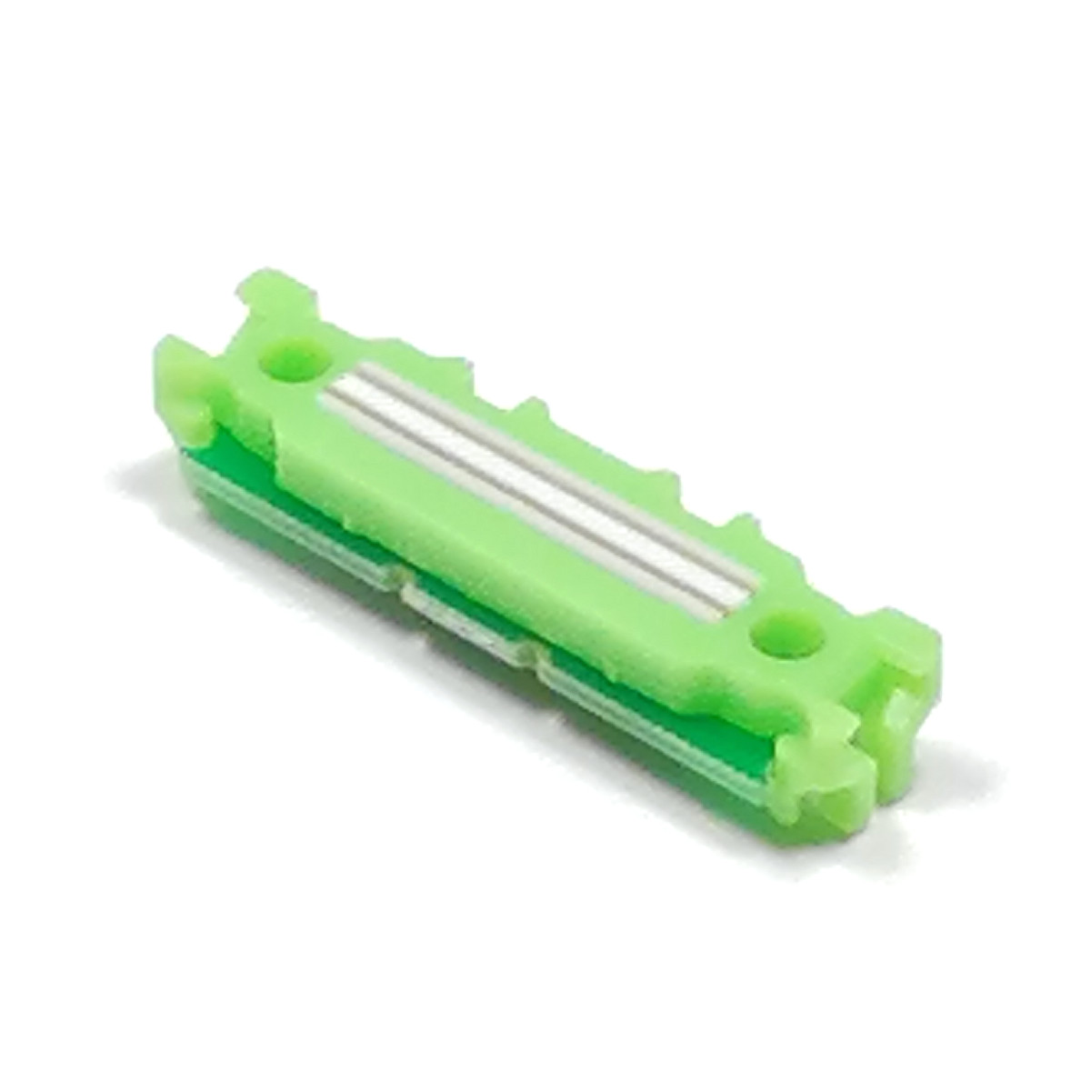
| AZ61 Connector | ACR (anisotropic conductive rubber) connectors between leaves |
| AZ62 Connector Cover | Protects exposed connectors from dirt |
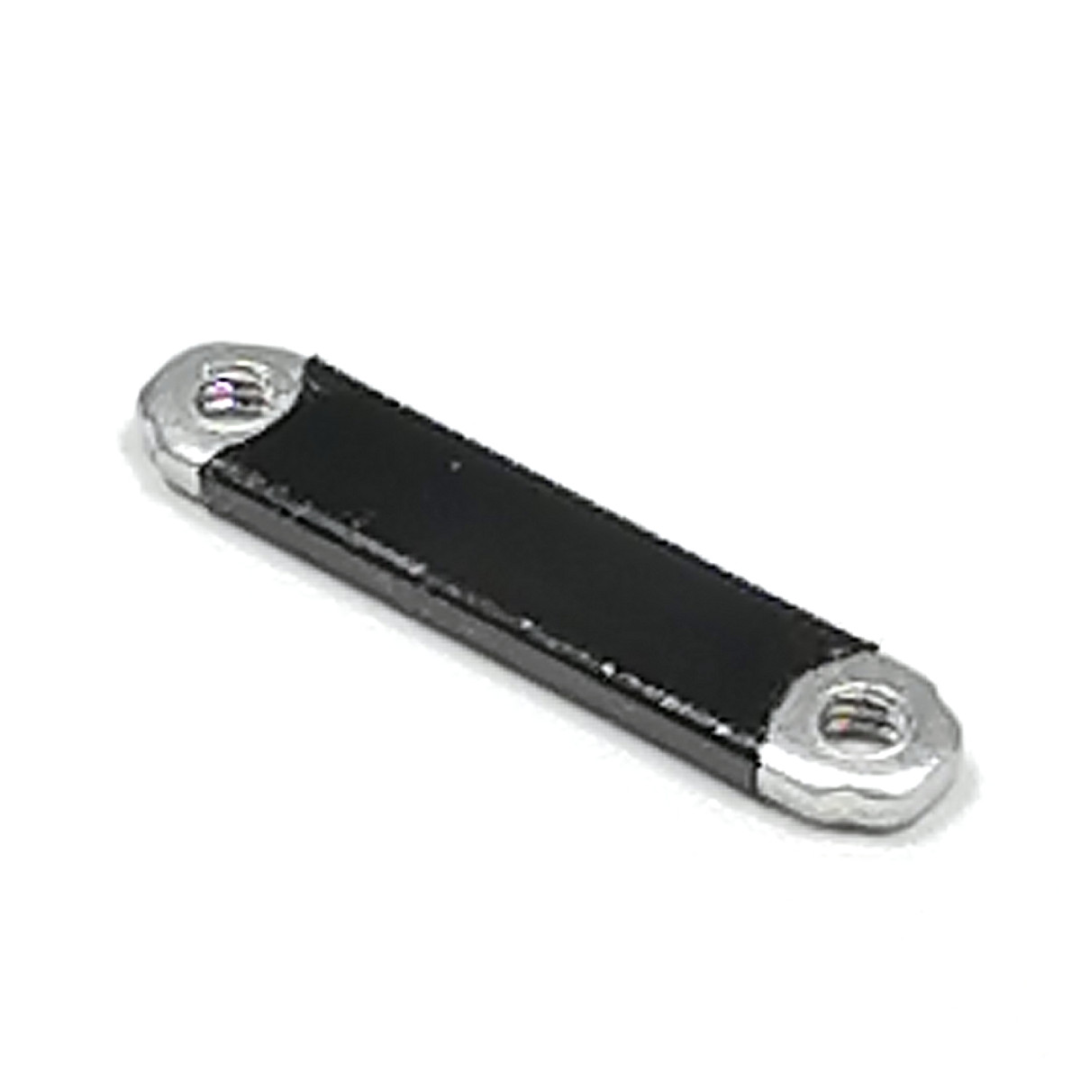
| Screws and AZ63 Nut Plate | Fasteners of the length and quantity specified for the configuration |
| AX04 Spacer | Used where the example specifies one or where adjacent components interfere |
| Kit or example assembly diagram | Stacking order and battery, USB, and external device connections |
If you do not know a leaf’s model, see How to Identify Your Leaves. Screw length and spacer requirements depend on the stack, so another kit’s fastening parts may not be suitable.
1. Disconnect All Power
Section titled “1. Disconnect All Power”Turn the power switch OFF and disconnect USB cables, batteries, and power from external circuits. Even with a power leaf’s switch OFF, check that no other source, such as USB, remains connected before removing the screws.
Take a photo of the existing stacking order so that you can restore it later.
2. Check Connectors and Orientation
Section titled “2. Check Connectors and Orientation”An ACR connector electrically connects the contacts when compressed between leaves. If a connector is detached, check the white line and attachment direction shown below.
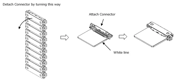
For removal, see the AZ61 attachment and removal diagrams. If a connector is dirty, check it using the power troubleshooting steps before stacking the leaves.
3. Follow the Assembly Diagram
Section titled “3. Follow the Assembly Diagram”Align the bus contacts and screw holes, and follow the front/back orientation and order in the kit or example diagram. If components touch another leaf or a board sits at an angle, do not force it into place with the screws. Review the configuration first.
Use an AX04 Spacer to increase clearance between components. Check the leaf or example documentation for the required position.
For a specific example, see Replacing AVR with STM32 in Basic Kit 2. The screws and stacking order in that example are for Basic Kit 2.
4. Secure the Stack Before Applying Power
Section titled “4. Secure the Stack Before Applying Power”Use the specified screws and Nut Plate. Tighten the screws alternately, checking for looseness or uneven alignment. Use AZ63 Nut Plate: ordinary hex nuts may touch the board contacts and cause a short circuit.
Before applying power, check the following:
- Bus contacts and screw holes align, and components do not touch each other.
- Connectors are in their correct positions and the screws are secure.
- Battery type and polarity match the power leaf’s input requirements.
- The program switch is in the correct position for running or uploading the program.
- If using USB and a battery together, the power conditions for each leaf have been checked.
After completing these checks, connect the power source specified by the kit or example.
5. Test a Simple Function First
Section titled “5. Test a Simple Function First”After replacement, use the development environment and program for the selected MCU. Start with a basic example, such as printing sensor readings to the serial monitor, to check connections and software in stages.
| Symptom | What to check next |
|---|---|
| No power | Power, connector, and screw checks |
| Upload fails | Upload troubleshooting |
| Communication stops after adding a leaf | Configuration checks and the I2C Address Map |
| Unsure which program to use | Development Environment and Examples |