
ESP32 MCU: Arduino IDE Setup
Set up with your favorite AI
 ChatGPT
  Claude
 Gemini & other AI
Copy the setup prompt into your AI. Work through each step together, from checking your kit to getting it running.
 Open Gemini
 Copy the prompt, then paste it into Gemini’s message box.
View prompt
Use Arduino IDE to set up the development environment for the AP02 ESP32 MCU leaf (ESP32-WROOM-32).
What to prepare
Section titled “What to prepare”- ESP32 Wi-Fi Kit
- Data-capable USB cable
- PC (Windows, macOS or Linux)
Installing Arduino IDE
Section titled “Installing Arduino IDE”- Open the Arduino website and go to SOFTWARE.
- Download the installer for your operating system.
- Run the installer and follow its instructions.
Previous IDE releases
Section titled “Previous IDE releases”Older versions are available from Previous IDE Releases.
Connecting to PC
Section titled “Connecting to PC”Connect to your PC with a USB cable.
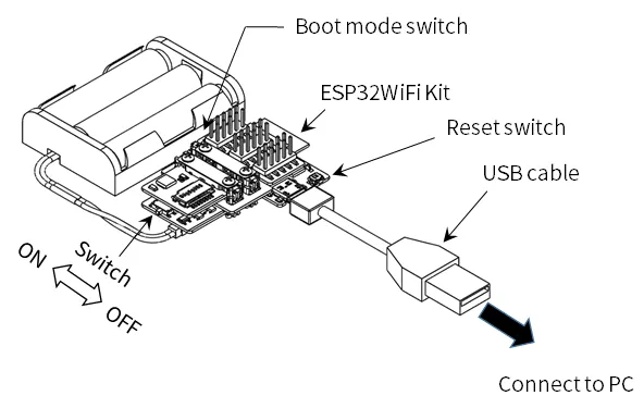
Configuration of the microcontroller board
Section titled “Configuration of the microcontroller board”Follow Espressif’s official installation guide for the package distribution URL. If an example specifies a core version, use that version.
To use the ESP32 MCU leaf with the Arduino IDE, you need to install Arduino core for the ESP32.
- Open the
File → Preferencesin the Arduino IDE and enter the following URL in theAdditional Board Manager URL:field.
https://espressif.github.io/arduino-esp32/package_esp32_index.json
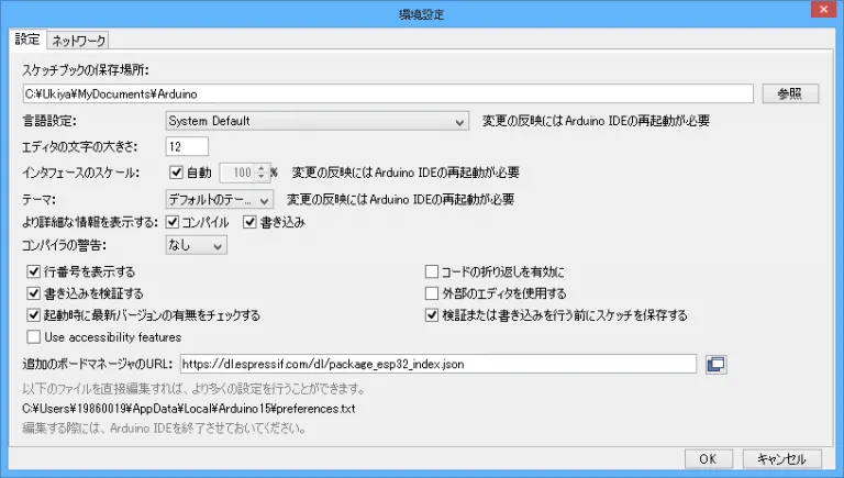
- Select
Tools -> Board -> Board Manager, search foresp32 by Espressif Systemsand press the Install button. Use the version selector if you need to select a specific version.
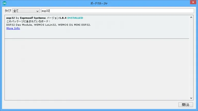
- Choose
Tools → Board → ESP32 Dev Module. - Choose the connected serial port from
Tools → Serial Port. If it is not listed, see Serial port not found.
Checking the operation of the microcontroller board
Section titled “Checking the operation of the microcontroller board”Uploading replaces the program currently on the MCU. To run the kit demo again later, follow Restore the demo.
Let’s write a Sample App and get the ESP32 Wi-Fi Kit running.
- Launch the Arduino.
- Paste the following sample code into your code editor.
//*****************************// ボタン入力の状態をシリアルモニタに表示するサンプル//*****************************int pushButton = 0;
void setup() {  Serial.begin(115200);  pinMode(pushButton, INPUT);}
void loop() { int buttonState = digitalRead(pushButton); Serial.println(buttonState); delay(1);}- Select the COM port to which the ESP32 leaf is connected.
- Push the
write to microcomputer boardbutton to write a sketch. - Press and hold the
Boot mode switchon the ESP32 leaf when the following message appears during the writing process.
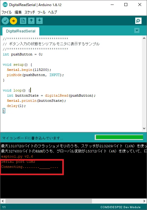
- Open the serial monitor and set the communication speed to
115200bps. - Press the
Boot mode switch (IO0)and see if the input state of the switch changes.

Specifying pins for a sketch
Section titled “Specifying pins for a sketch”Pin should be specified by Port, not Name.

Restrictions
Section titled “Restrictions”※1:Output cannot be set
※2:①For UART1, the pin number is set to RX=26 and TX=25. For UART0 and UART2, the pin number is not specified.
HardwareSerial Serial1(1); // UART1 (RX=9, TX=10)
void setup() {  Serial1.begin(9600, SERIAL_8N1, 26, 25); // ピンを変更 (RX=26, TX=25)}
②Cannot be used as analog input if WiFi.h is included
※3: Pull-up prohibited because it is used for bootstrapping
Installing Libraries
Section titled “Installing Libraries”Install only the libraries required by your example. See Libraries and board definitions for sources and installation steps. The button-input example above needs no additional libraries.
When in doubt.
Section titled “When in doubt.”If it doesn’t work, go to “If it doesn’t work…” to find a solution.