Illum sensor
Overview
Section titled “Overview”This sample reads the value of the illuminance sensor mounted on the 4-Sensors leaf and displays it on the serial monitor.
Leaf to use
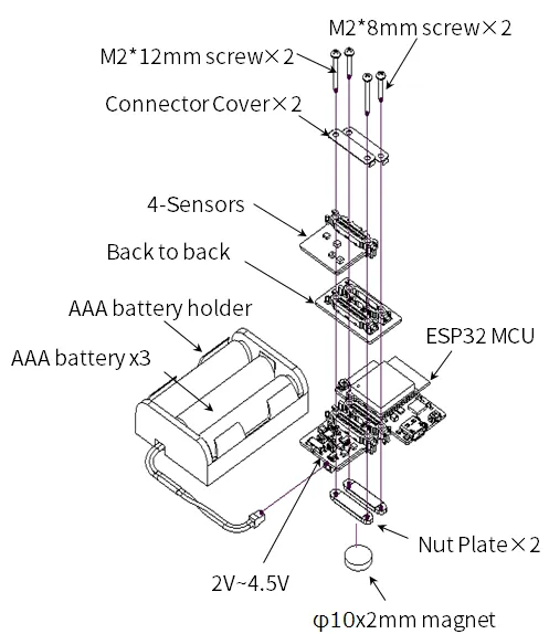
Section titled “Leaf to use”Use the following leaf.
| Type | Name | Q’ty |
|---|---|---|
| AZ62 | Connector Cover | 2 |
| AI01 | 4-Sensors | 1 |
| AX07 | Back to back | 1 |
| AP02 | ESP32 MCU | 1 |
| AV04 | 2V~4.5V | 1 |
| AZ63 | Nut Plate | 2 |
| AAA battery holder | 1 | |
| AAA battery | 3 | |
| M2*8mm screw | 2 | |
| M2*12mm screw | 2 | |
| φ10x2mm magnet | 1 |
Assembly
Section titled “Assembly”Let’s assemble leaves as shown in the figure below.
Source code
Section titled “Source code”Write the following program in the Arduino IDE.
In order to make this sketch work, you need to install the libraries If you haven’t installed it yet, refer to Environment to install it.
//=====================================================================//  Illuminance meter////    (c) 2020 Trillion-Node Study Group//    Released under the MIT license//    https://opensource.org/licenses/MIT////      Rev.00 2020/05/05  First release//=====================================================================#include <Wire.h>#include <ClosedCube_OPT3001.h>
#define OPT3001_ADDRESS 0x45      // ADDR pin = VCC
ClosedCube_OPT3001 illum;
float dataIllum;
void setup() {  // initialize serial communication at 115200 second per second:  Serial.begin(115200);  // initialize i2c communication with OPT3001:  Wire.begin();
  delay(10);
  OPT3001_Config illumConfig;  OPT3001_ErrorCode illumErrorConfig;
  illum.begin(OPT3001_ADDRESS);
  illumConfig.RangeNumber = B1100;               // automatic full scale  illumConfig.ConvertionTime = B1;               // convertion time = 800ms  illumConfig.ModeOfConversionOperation = B11;   // continous conversion  illumConfig.Latch = B0;                        // hysteresis-style
  illumErrorConfig = illum.writeConfig(illumConfig);
  if(illumErrorConfig != NO_ERROR){    illumErrorConfig = illum.writeConfig(illumConfig);   //retry  }}
void loop() {    OPT3001 result = illum.readResult();
    if(result.error == NO_ERROR){      dataIllum = result.lux;    }
    Serial.println("Lum[lx] = " + String(dataIllum));
    delay(1000);
}Execution Results
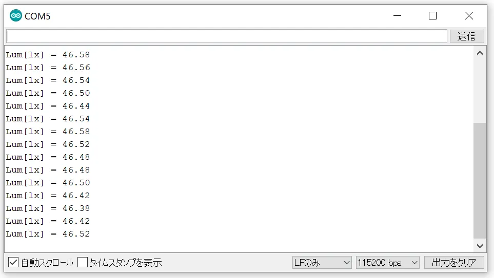
Section titled “Execution Results”Open the serial monitor in the Arduino IDE and set the baud rate to 115200 bps, and you will see the illumination.