
AI05 Env Sensors
Documentation: Specifications and connections available; sensor example in preparation
Explore with your favorite AI
 ChatGPT
  Claude
 Gemini & other AI
Copy this page’s context into your AI to explore how it works and what you can build.
 Open Gemini
 Copy the prompt, then paste it into Gemini’s message box.
View prompt
Features
Section titled “Features”This leaf measures temperature, humidity, pressure and 3-axis acceleration. Combine it with an MCU (microcontroller) leaf to read environmental conditions and the leaf’s tilt and motion.
The standard configuration uses a BME280 temperature, humidity and pressure sensor and a LIS2DW12 3-axis accelerometer. It operates from the Leafony Bus 3.3 V supply, and readings are obtained over I2C. A four-pin connector is available for external I2C devices.
Pads are also provided for SHT40, SGP40 and BME680 sensors. These are not fitted as standard. Using them requires the components and program described under optional assembly.
Specifications
Section titled “Specifications”Board and interfaces
Section titled “Board and interfaces”| Item | Description |
|---|---|
| Board dimensions | 23 × 20 mm |
| Board thickness | 0.8 mm (excluding component height) |
| Board layers | 4 |
| Power and signal voltage | 3.3 V |
| Communication | I2C, up to 400 kHz |
| Acceleration interrupt | LIS2DW12 INT1 connected to Leafony Bus D3 |
| External connector J1 | 4 pins, 2.54 mm pitch, for a right-angle pin header |
| SDA/SCL pull-ups | R18 and R19 (2.7 kΩ each) are not fitted as standard |
Standard configuration
Section titled “Standard configuration”| Reference | Part | Manufacturer | Measurements |
|---|---|---|---|
| U3 | BME280 | Bosch Sensortec | Temperature, humidity and pressure |
| U5 | LIS2DW12TR | STMicroelectronics | 3-axis acceleration |
The BME280 operating temperature range is −40 to 85 °C, and the pressure measurement range is 300 to 1100 hPa. Accuracy conditions depend on temperature; see the BME280 manufacturer documentation.
The LIS2DW12 acceleration range can be set to ±2 g, ±4 g, ±8 g or ±16 g (manufacturer documentation).
Optional assembly
Section titled “Optional assembly”DNP (Do Not Populate) means the component is not fitted.
| Reference | Part | Function | Standard configuration |
|---|---|---|---|
| U1 | SHT40-AD1B-R2 | Temperature and humidity | DNP |
| U2 | SGP40-D-R4 | Gas sensor responding to volatile organic compounds (VOCs) | DNP |
| U4 | BME680 | Temperature, humidity, pressure and gas sensor | DNP |
The BME280 (U3) and BME680 (U4) have separate footprints, but only one is fitted. Both use I2C address 0x76, so they cannot both be fitted and read independently.
The standard configuration populates U3, C21 and C22, leaving U4, C23 and C24 unpopulated. Reverse that choice to use BME680. SHT40 and SGP40, which are not fitted as standard, will not respond to an I2C scan.
When adding SHT40, also fit C20. When adding SGP40, also fit R10 (4.7 Ω), C2 and C3. These are also unpopulated as standard; without R10, SGP40 receives no power.
Gas measurement is not included in the standard configuration. Using metrics such as SGP40’s VOC Index requires the sensor and corresponding signal processing (SGP40 manufacturer information, BME680 manufacturer information).
I2C addresses
Section titled “I2C addresses”All addresses use 7-bit notation.
| Device | Address | Configuration |
|---|---|---|
| LIS2DW12 | 0x18 | Standard; SDO/SA0 connected to GND |
| BME280 | 0x76 | Standard; SDO connected to GND |
| SHT40 | 0x44 | Optional |
| SGP40 | 0x59 | Optional |
| BME680 | 0x76 | Alternative to BME280; SDO connected to GND |
Pin connections
Section titled “Pin connections”Leafony Bus
Section titled “Leafony Bus”| Signal | Connector contacts | AI05 function |
|---|---|---|
| V33 | F1 / B1 | 3.3 V power |
| SDA | F23 / B23 | I2C data |
| D3 | F24 / B24 | LIS2DW12 INT1 interrupt |
| SCL | F25 / B25 | I2C clock |
| GND | F27 / B27 | Power and signal ground |
F/B are the front/back contact names on the KiCad Leafony Bus connector CN1. LIS2DW12 INT2 is not connected. See the Leafony Bus for the overall bus specification.
External I2C connector J1
Section titled “External I2C connector J1”| Pin | Signal | Function |
|---|---|---|
| 1 | GND | Power and signal ground |
| 2 | +3.3V | Leafony Bus 3.3 V supply |
| 3 | SDA | I2C data |
| 4 | SCL | I2C clock |
J1 accepts a four-pin, 2.54 mm pitch header and shares the Leafony Bus power and I2C bus. Check pin numbers and 3.3 V compatibility before attaching cables or external devices.
Connection requirements
Section titled “Connection requirements”- Check the I2C pull-ups. R18 and R19 are not fitted. When paired with AP03 STM32 MCU, the pull-ups on AP03 are used. For other MCUs and external devices, also check that SDA/SCL are pulled up to 3.3 V.
- The I2C address conflicts with AX06 Grove&5V. AI05’s LIS2DW12 and AX06’s I/O expander both use
0x18. Do not connect them to the same bus with their standard settings. - The D3 interrupt line conflicts with AI01 4-Sensors. AI05 uses acceleration address
0x18and AI01 uses0x19, but the interrupt line is shared, so do not combine them unchanged. If SHT40 is added,0x44may also conflict, depending on the address setting of AI01’s light sensor. - Devices connected to J1 also share the I2C bus. Check the I2C address map for conflicts with other leaves.
PCB layout
Section titled “PCB layout”These reference images were generated from the KiCad board data. They omit component 3D models and include pads for optional components. See standard configuration and optional assembly for fitted and unpopulated components.
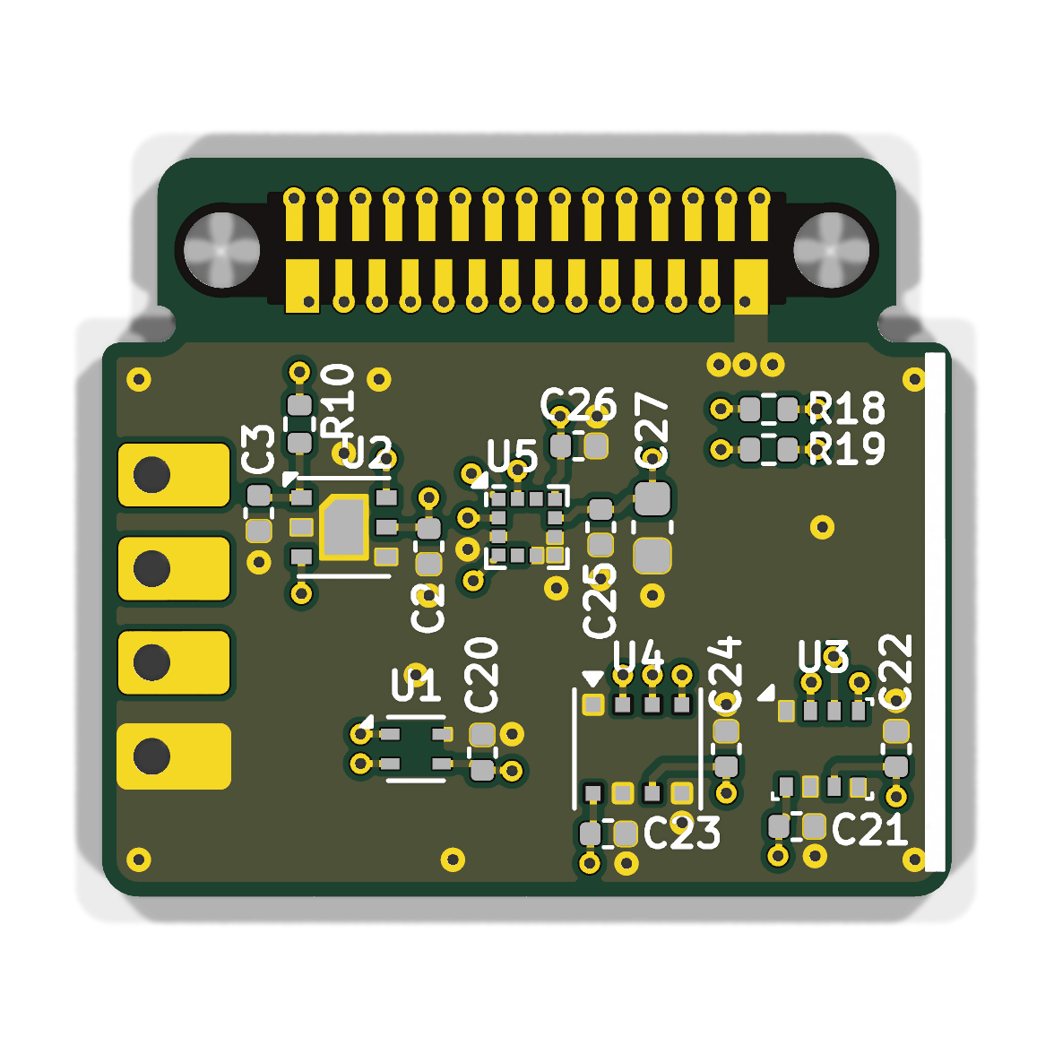
Bottom
Section titled “Bottom”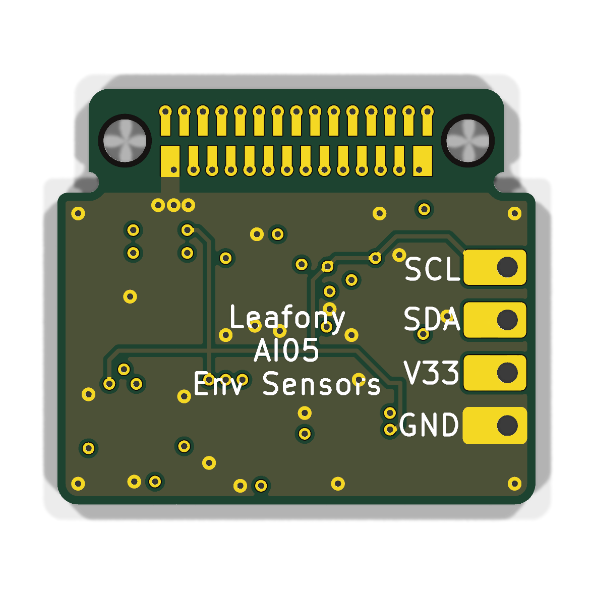
Software
Section titled “Software”Initialize I2C on the MCU and read BME280 at 0x76 and LIS2DW12 at 0x18. Follow each manufacturer’s documentation for initialization, compensation calculations and register settings.
AI01 4-Sensors uses different sensors, so its temperature/humidity and acceleration examples cannot be used unchanged. The referenced repository does not yet include AI05 example programs.
Documents
Section titled “Documents”- AI05 Env Sensors repository
- KiCad project
- KiCad schematic
- KiCad PCB layout
- Panelized manufacturing data
- BME280 manufacturer information
- LIS2DW12 manufacturer information
- SHT40 manufacturer information
- SGP40 manufacturer information
- BME680 manufacturer information
Revision history
Section titled “Revision history”- September 2026: Initial version.