
AX05B I Meas Current Measurement Leaf
Explore with your favorite AI
 ChatGPT
  Claude
 Gemini & other AI
Copy this page’s context into your AI to explore how it works and what you can build.
 Open Gemini
 Copy the prompt, then paste it into Gemini’s message box.
View prompt
| Top | Bottom |
|---|---|
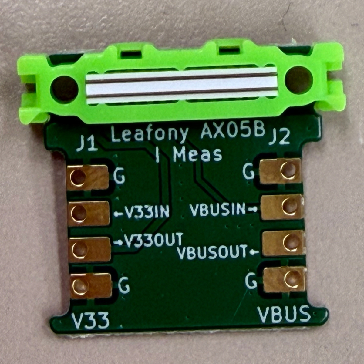 | 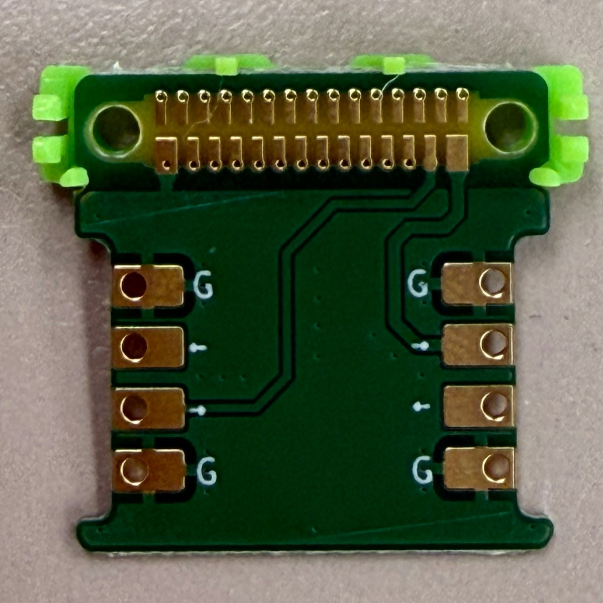 |
Features
Section titled “Features”Leafony AX05B I Meas is a leaf for measuring current on the V33 and VBUS lines of the Leafony Bus. It separates each power line into IN and OUT so an external current measurement instrument, such as the Nordic Power Profiler Kit II (PPK2), can be inserted in series.
It separates the power supply connections of the leaves stacked below AX05B from those stacked above it, allowing you to measure the current flowing to the upper leaves.
Each power line coming from the lower leaves is split into IN and OUT on AX05B. Connect the current measurement instrument in series on the line you want to measure, and short IN and OUT with a jumper on the line you are not measuring.
- Supports current measurement on the Leafony Bus
V33andVBUSlines - Provides 2.54 mm pitch right-angle pin headers for both
V33andVBUS - Power lines that are not being measured can be shorted with jumpers for normal use
Specification
Section titled “Specification”| Item | Description |
|---|---|
| Dimension | W20×D20mm |
| Board thickness | 0.8mm |
| Layer | 2 layers |
| Surface finish | ENIG (Immersion gold) |
| Bus connector | Leafony Bus (F29/B29) |
| Measurement connector | 1×4, 2.54 mm pitch, right-angle pin header ×2 |
Package contents
Section titled “Package contents”AX05B I Meas includes the board, two single-row four-pin right-angle pin headers, and two jumper pins.
| Board | Included parts |
|---|---|
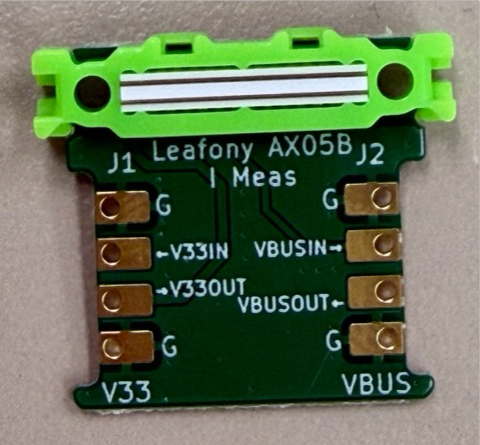 | 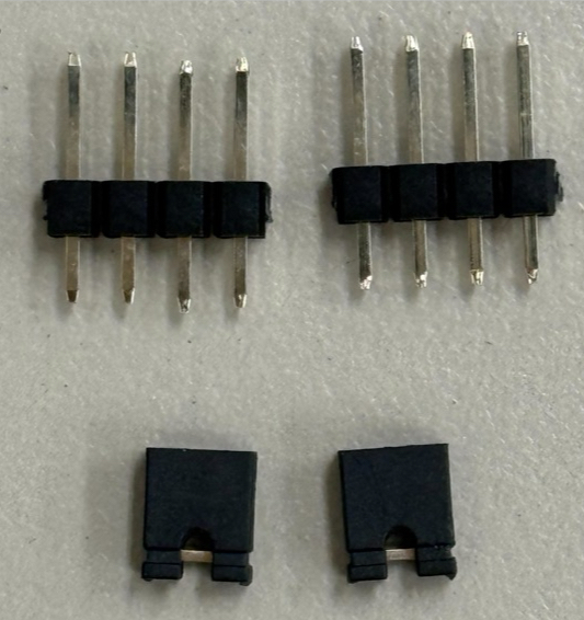 |
Measurement connector
Section titled “Measurement connector”J1 is for V33, and J2 is for VBUS. Both connectors use the same pin assignment.
| Pin | J1 (V33) | J2 (VBUS) | Use |
|---|---|---|---|
| 1 | GND | GND | Measurement instrument GND |
| 2 | V33OUT | VBUSOUT | Current flowing out to the top side of the leaf |
| 3 | V33IN | VBUSIN | Current flowing in from the bottom side of the leaf |
| 4 | GND | GND | Measurement instrument GND |
Current measurement with Nordic Power Profiler Kit II
Section titled “Current measurement with Nordic Power Profiler Kit II”The Nordic Power Profiler Kit II (PPK2) is a current logger that can measure both the tiny currents drawn by low-power IoT devices during sleep and the milliamp-level currents drawn while they are active. It can also operate as a source measurement unit (SMU), providing power while measuring current.
This makes it a useful tool for developing battery-powered IoT devices, including Leafony applications.
Follow these steps to measure current with the PPK2.
-
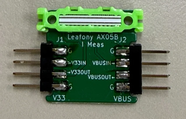
Solder the included single-row four-pin headers onto the leaf as shown below.
-
Connect the PPK2 pins to the
V33connector as shown in the table. To insert the PPK2 as an ammeter in series with the power line, connectVINtoV33INandVOUTtoV33OUT.PPK2 AX05B J1 (V33) Use GNDGNDGND VINV33INPower coming from the lower leaves VOUTV33OUTPower going to the upper leaves GNDGNDGND 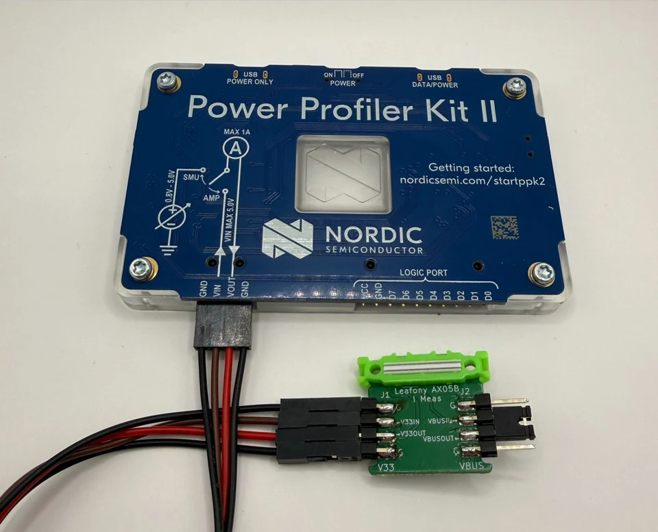
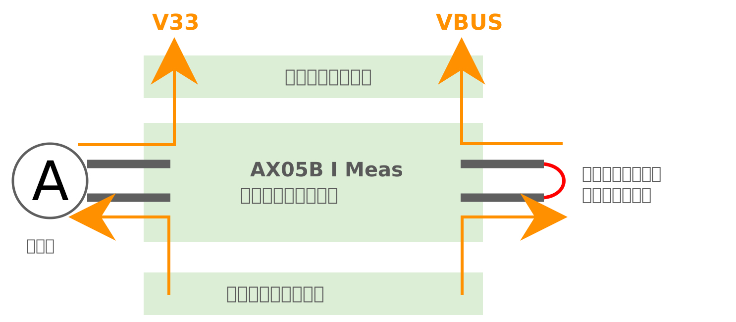
Place AX05B between the lower leaves and the upper leaves you want to measure. The
V33supply from the lower leaves passes through the ammeter connected to AX05B before reaching the upper leaves. When using a single ammeter, such as the PPK2, short the unmeasuredVBUSline with a jumper pin so that power reaches the upper leaves. -
Since
VBUSis not being measured in this example, shortVBUSINandVBUSOUTwith one of the included jumper pins. -
Assemble the stack with the leaves whose current you want to measure above AX05B and all other leaves below it.
-
Turn on the power, operate the PPK2 in ammeter mode, and click Start to begin measuring current. In the Power Profiler app, this mode is called Ampere meter, as shown in the official PPK2 quick start.
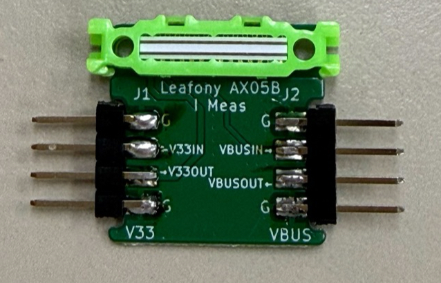
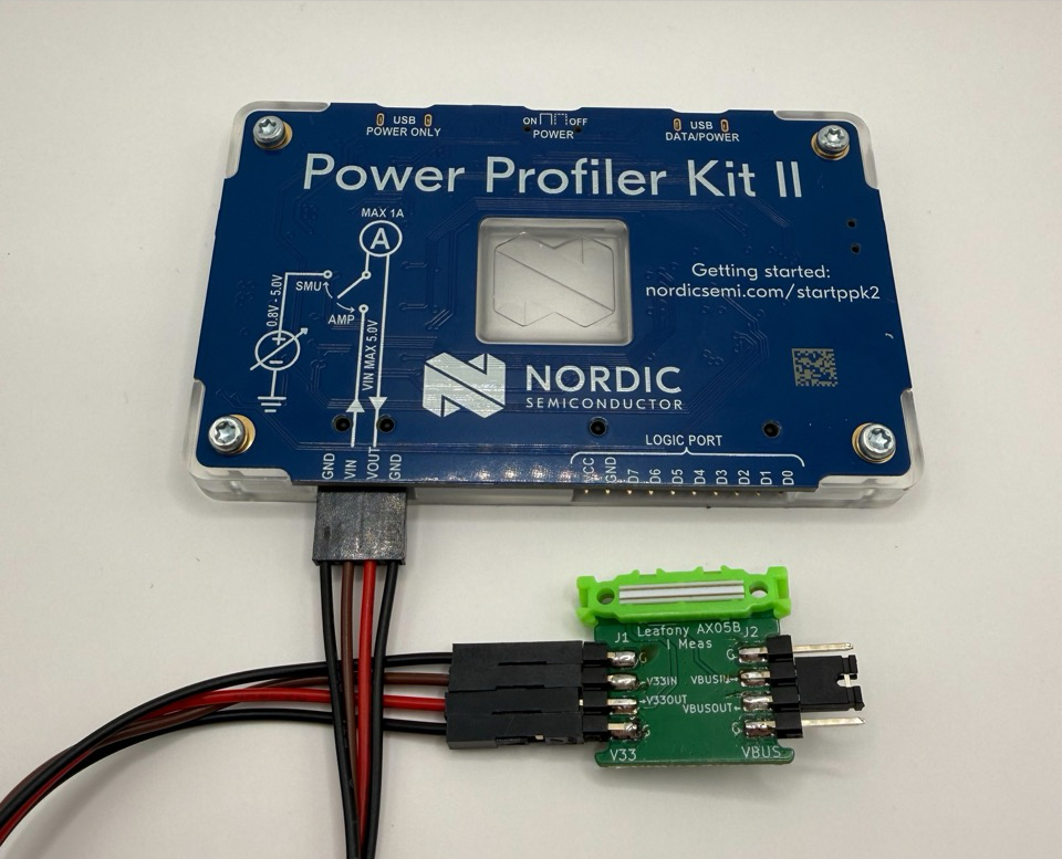
For information on using the PPK2, see the official page (Japanese).
Documents
Section titled “Documents”- GitHub repository
- KiCad project
- Schematic (PDF)
- PCB layout (PDF)
- Schematic (KiCad)
- PCB layout (KiCad)
- Panelized manufacturing data
Revision history
Section titled “Revision history”- June 2026: First edition