
Low-Power IoT Sensor Design and Battery Runtime Calculations
Explore with your favorite AI
 ChatGPT
  Claude
 Gemini & other AI
Copy this page’s context into your AI to explore how it works and what you can build.
 Open Gemini
 Copy the prompt, then paste it into Gemini’s message box.
View prompt
Leafony is designed for compact, battery-powered systems. Runtime depends on the complete circuit, its program and its power supply. Start by identifying where energy is spent, then measure the assembled device.
Thinking about low-power design
Section titled “Thinking about low-power design”When building a circuit, consider both its power consumption and whether the intended supply can provide enough power. USB supplies and AC adapters can often supply a few watts for long periods. A battery-powered device also needs to make its limited stored energy last.
A larger battery can extend runtime, but a small device such as a wristwatch needs a small battery. Small changes in consumption can then have a large effect on runtime. For a compact system such as Leafony, low-power design is an important part of its performance.
Power and energy
Section titled “Power and energy”For a constant voltage and current, power is P = V × I. One watt is one volt times one ampere. Energy is power multiplied by time: 1 Wh = 1 W × 1 h.
Measure current at the battery to calculate the complete circuit’s power. Individual components draw different currents, and their current can change with their operating state. A resistor’s current is determined by the applied voltage and resistance, whereas an IC’s internal activity affects its current. Battery voltage can also change during use.
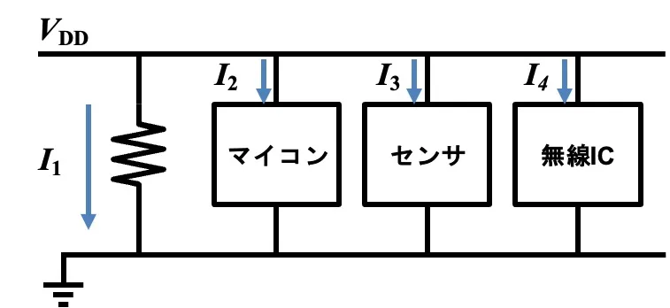
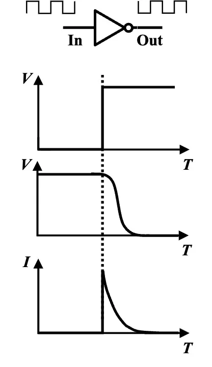
ICs contain analog or digital circuits. In digital circuits such as CPUs, logic gates are commonly built from MOSFETs. In the simplified example below, a NOT gate draws a large pulse of current when its input changes. A 0 V input (LOW) produces a 5 V output (HIGH); when the input rises to 5 V, the output falls toward 0 V.
The top trace shows the input transition, the middle trace shows the output response, and the bottom trace shows the current pulse. Here, the current while the input remains unchanged is called leakage current, and the current associated with switching is called dynamic current. This example ignores leakage to focus on switching power.
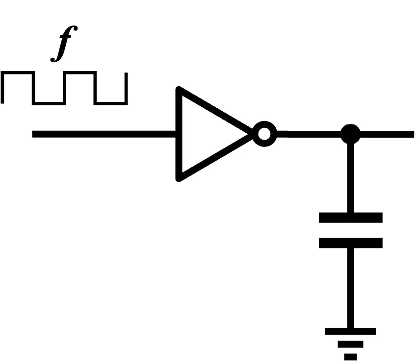
The following example applies a clock of frequency f to a NOT gate. Wiring and the inputs of subsequent gates contribute parasitic load capacitance at its output. For switching in a digital circuit, a simplified model is:
P = α * C * V^2 * fHere P is average switching power, C is load capacitance, V is supply voltage, f is clock frequency, and α is the number of charging events per clock cycle. This excludes leakage and short-circuit current. Under these assumptions, power is proportional to clock frequency. A faster CPU clock can increase processing speed as well as power consumption.
Identify the loads
Section titled “Identify the loads”Knowing that power depends on frequency does not tell us the number of logic gates or the capacitance inside an IC. We can estimate its consumption from the manufacturer’s data sheet without knowing every detail of its internal circuit.
| Leaf | Main device | Conditions to compare |
|---|---|---|
| AP01 AVR MCU | ATmega328P | Clock frequency, active and sleep states, enabled peripherals |
| AP03 STM32 MCU | STM32L452REI6 | 16 / 80 MHz, run / sleep / stop, RTC and other peripherals |
| AI01 4-Sensors | HTS221TR, OPT3001, LIS2DHTR | Measurement interval, continuous / single measurement / power-down |
| AC02 BLE Sugar | BGM11S22F256GA-V2 | Transmit power, interval, connection / beacon / sleep |
Follow the specifications and schematic links in each reference page, then consult the component data sheets at the actual supply voltage, temperature and operating mode. This table identifies what to investigate; it is not a table of measured current. Include LEDs, resistors and power converters when measuring a complete leaf.
Record the leaf model and revision, firmware, supply voltage, instrument, temperature, mode, measurement interval and average current. Distinguish typical values from maximum values, and data-sheet values from measurements.
Estimate battery runtime
Section titled “Estimate battery runtime”Battery charge capacity is measured in ampere-hours: 1 Ah = 1 A × 1 h. Multiply by nominal voltage to estimate stored energy.
One ampere-hour is the charge needed to supply one ampere for one hour. It does not specify voltage: a 1 Ah battery at 1.5 V stores a different amount of energy from one at 3 V. Watt-hours let us compare batteries at different voltages, although changing battery voltage makes an exact energy calculation more complex.
The following are assumed values for arithmetic examples, not specifications for all products:
| Example battery | Assumed nominal voltage and capacity | Nominal energy |
|---|---|---|
| CR2032 coin cell | 3.0 V, 220 mAh | 660 mWh |
| AA nickel-metal hydride cell | 1.2 V, 2,000 mAh | 2,400 mWh |
| Lithium-ion cell | 3.7 V, 3,000 mAh | 11,100 mWh |
The CR2032 in this example stores about 28% of the energy of the AA cell. Actual capacity depends on the product, temperature and discharge conditions; check the data sheet for the battery you plan to use.
A constant 3.3 V, 100 mA load consumes 330 mW. Under the assumptions above, a 660 mWh battery gives 660 / 330 = 2 h; a 2,400 mWh battery gives approximately 7.3 h.
A load that sleeps between measurements
Section titled “A load that sleeps between measurements”Assume a circuit draws 100 mA for one minute each hour and 1 mA for the remaining 59 minutes, all at 3.3 V.
Average current = 100 mA × 1/60 + 1 mA × 59/60 = 2.65 mAAverage power = 3.3 V × 2.65 mA = 8.745 mWEnergy used in one hour = 8.745 mWhIdeal runtime = 660 mWh / 8.745 mW ≈ 75.5 h ≈ 3.14 daysThis is a theoretical example, not a measured Leafony runtime.
Reduce energy use
Section titled “Reduce energy use”The following techniques are used in the STM32 Logger Beacon sample.
Lower the clock frequency when possible
Section titled “Lower the clock frequency when possible”The CPU is a major digital circuit in a Leafony system. The STM32 leaf defaults to 80 MHz, and Leafony provides both 80 MHz and 16 MHz board options. Selecting a lower clock trades processing performance for lower switching power.
In Arduino IDE, open Tools → Board part number → Leafony STM32 MCU and select the required frequency. See the Arduino setup guide for the board package settings.
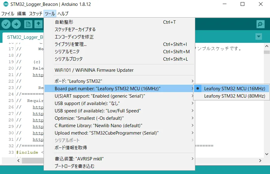
Choose a frequency based on whether the application needs fast computation or prioritizes low-power operation. Another approach is to get the sketch working at a higher frequency, then reduce the frequency and test its behavior at each available setting.
Put unused circuits to sleep or power them down
Section titled “Put unused circuits to sleep or power them down”Each component uses energy, even if it is temporarily unnecessary. For example, a system can read the four measurements from 4-Sensors and then send them through a BLE leaf. The sensor ICs are not needed during BLE transmission, so putting them into sleep modes after reading reduces consumption. This matters especially when running from a coin cell.
The STM32 chip also contains multiple internal circuits whose sleep states can be controlled separately to reduce consumption.
Wake the CPU with interrupts
Section titled “Wake the CPU with interrupts”When the circuit only needs to react to external events, use the CPU’s interrupt functions to wake it from sleep when needed.
Measure and verify
Section titled “Measure and verify”- Record the leaves, firmware, battery and voltage.
- Measure current on the battery side over a complete cycle, including startup, sensing, radio transmission and sleep. Check that the instrument’s voltage drop does not affect operation.
- Average current over time. If voltage changes, average the product of voltage and current to obtain average power.
- Change one setting at a time and compare with the estimate.
- Verify runtime using the intended battery and operating temperature.
Only the arithmetic examples have been checked for this revision. No hardware test date, instrument record or verified firmware revision is recorded for this page.
For choosing a measurement location, connecting AX05B and a current meter, and comparing complete active/sleep cycles, see Measure Current and Reduce Power Consumption.