照度センサ読み取り
4-Sensorsリーフに搭載された照度センサの値を読み取って、シリアルモニタに表示するサンプルです。
使用するリーフ
Section titled “使用するリーフ”以下のリーフを使用します
| Type | Name | Q’ty |
|---|---|---|
| AZ62 | Connector Cover | 1 |
| AI01 | 4-Sensors | 1 |
| AZ01 | USB | 1 |
| AP03 | STM32 MCU | 1 |
| AV01 | CR2032 | 1 |
| CR2032 coin cell battery | 1 | |
| M2*15mm screw | 2 |
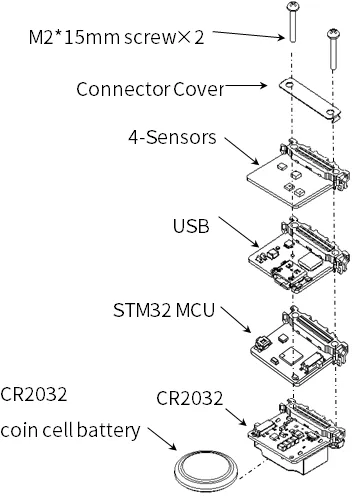
リーフの組み立て
Section titled “リーフの組み立て”下図を参考にリーフを組み立ててみましょう。
ソースコード
Section titled “ソースコード”Arduino IDEで下記のプログラム1を書きましょう。
このスケッチを動かすためには、ライブラリのインストールが必要です。 まだインストールしていない場合は開発環境設定ページを参考にライブラリをインストールしてください。
//=====================================================================// Illuminance meter//// (c) 2021 LEAFONY SYSTEMS Co., Ltd// Released under the MIT license// https://opensource.org/licenses/MIT//// Rev.00 2021/04/01 First release//=====================================================================#include <Wire.h>#include <ClosedCube_OPT3001.h>
#define OPT3001_ADDRESS 0x45 // ADDR pin = VCC
ClosedCube_OPT3001 illum;
float dataIllum;
void setup() { // initialize serial communication at 115200 second per second: Serial.begin(115200); // initialize i2c communication with OPT3001: Wire.begin();
delay(10);
OPT3001_Config illumConfig; OPT3001_ErrorCode illumErrorConfig;
illum.begin(OPT3001_ADDRESS);
illumConfig.RangeNumber = B1100; // automatic full scale illumConfig.ConvertionTime = B1; // convertion time = 800ms illumConfig.ModeOfConversionOperation = B11; // continous conversion illumConfig.Latch = B0; // hysteresis-style
illumErrorConfig = illum.writeConfig(illumConfig);
if(illumErrorConfig != NO_ERROR){ illumErrorConfig = illum.writeConfig(illumConfig); //retry }}
void loop() { OPT3001 result = illum.readResult();
if(result.error == NO_ERROR){ dataIllum = result.lux; }
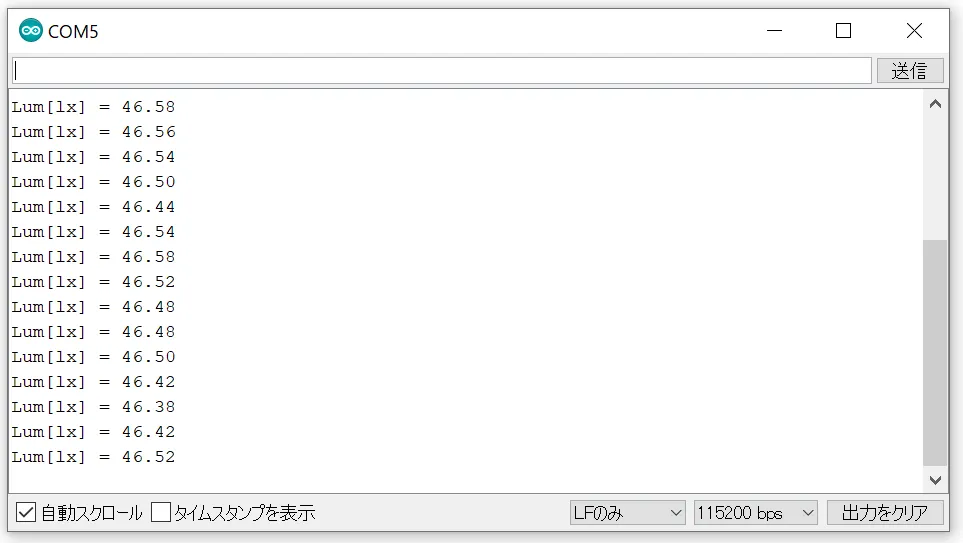
Serial.println("Lum[lx] = " + String(dataIllum));
delay(1000);
}Arduino IDEのシリアルモニタを開き、ボーレートを115200bpsとすると、照度が表示されます。
Footnotes
Section titled “Footnotes”-
プログラムは、AVR MCUリーフと同じです。 ↩