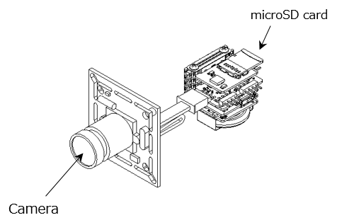
Camera
Overview
An example of using Seeed Studio’s Grove series sensors. Let’s try to save an image taken by the camera once a minute to a microSD card.
Leaf to use
| Type | Name | Q’ty |
|---|---|---|
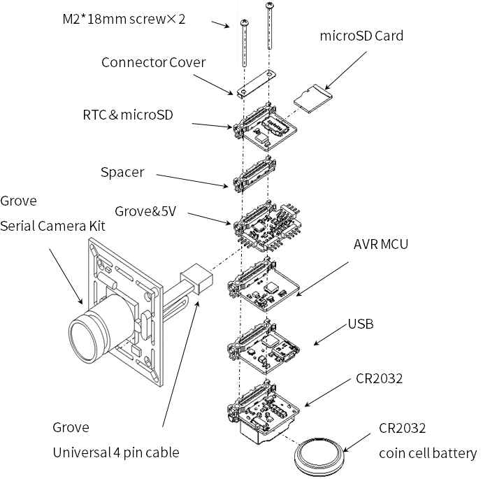
| AZ62 | Connector Cover | 1 |
| AZ02 | RTCµSD | 1 |
| AX04 | Spacer | 1 |
| AX06 | Grove&5V | 1 |
| AP01 | AVR MCU | 1 |
| AZ01 | USB | 1 |
| AV01 | CR2032 | 1 |
| CR2032 coin cell battery | 1 | |
| Grove-Serial Camera Kit | 1 | |
| microSD card | 1 | |
| M2*18mm screw | 2 |
Assembly
Source code
- 4-Sensors and AVR MCU library (timer interrupt) are required for writing. Please include the library beforehand. For details, see here.
- Write the following program in the Arduino IDE.
//=====================================================================
//  Leafony Platform sample sketch
//     Platform     : Grove + Camera
//     Processor    : ATmega328P (3.3V /8MHz)
//     Application  : Camera
//
//     Leaf configuration
//       (1) AP01 AVR MCU
//       (2) AX01 Grove&5V + Grove Serial Camera Kit
//       (3) AZ01 USB
//       (4) AZ02 RTC&MicroSD
//
//		(c) 2019  Trillion-Node Study Group
//		Released under the MIT license
//		https://opensource.org/licenses/MIT
//
//      Rev.00 2019/08/01 First release
//=====================================================================
//use libraries
//=====================================================================

//=====================================================================
// difinition
//=====================================================================
#include <MsTimer2.h>
#include <SPI.h>
#include <SD.h>
#include <SoftwareSerial.h>
#include <avr/wdt.h>
#include <avr/sleep.h>
#include <avr/power.h>
//=====================================================================

#define DEBUG

//=====================================================================
// SPI CLOCK
// SDカードのSPI I/Fのクロック速度4Mでは動作しないので4M以下に設定すること
//=====================================================================
#define SD_CLCK 2500000

//=====================================================================
// 撮影間隔(秒)
//
//=====================================================================
#define SNAP_WAIT 60

//=====================================================================
// IOピンの名前定義
// 接続するリーフに合わせて定義する
//=====================================================================
// --------------------------------------------
// PD port
//     digital 0: PD0 = PCRX    (HW UART)
//     digital 1: PD1 = PCTX    (HW UART)
//     digital 2: PD2 = INT0#
//     digital 3: PD3 = INT1#
//     digital 4: PD4 = RSV
//     digital 5: PD5 = RSV
//     digital 6: PD6 = RSV
//     digital 7: PD7 = RSV
// --------------------------------------------
#define PCTX    0
#define PCRX    1
#define INT0    2
#define INT1    3
#define RSV_D4  4
#define RSV_D5  5
#define SD_EN   6
#define RSV_D7  7

// --------------------------------------------
// PB port
//     digital 8: PB0 = UART2_RX (software UART)  /* not use */
//     digital 9: PB1 = UART2_TX (software UART)  /* not use */
//     digital 10:PB2 = CS#
//     digital 11:PB3 = MOSI
//     digital 12:PB4 = MISO
//     digital 13:PB5 = SCK (AVR LED)
//                PB6 = XTAL1
//                PB7 = XTAL2
//---------------------------------------------
#define UART2_RX   8
#define UART2_TX   9
#define SD_CS     10
#define MOSI      11
#define MISO      12
#define LED_PIN   13

// --------------------------------------------
// PC port
//     digital 14/ Analog0: PC0 = RSV
//     digital 15/ Analog1: PC1 = CAMERA TX (software UART)
//     digital 16/ Analog2: PC2 = CAMERA RX (software UART)
//     digital 17/ Analog3: PC3 = RSV
//     digital 18/ SDA    : PC4 = SDA   (I2C)
//     digital 19/ SCL    : PC5 = SCL   (I2C)
//     RESET              : PC6 = RESET#
//-----------------------------------------------
#define RSV_D14   14
#define UART3_TX  15
#define UART3_RX  16
#define RSV_D17   17
#define SDA       18
#define SCL       19
//=====================================================================

//=====================================================================
// camera
//=====================================================================
//Color Setting
#define COLOR_2BIT_GRAY   0x01
#define COLOR_4BIT_GRAY   0x02
#define COLOR_8BIT_GRAY   0x03
#define COLOR_2BIT_COLOR  0x05
#define COLOR_4BIT_COLOR  0x06
#define COLOR_JPEG        0x07
//Preview Resolution
#define PRE_RES_80_60     0x01
#define PRE_RES_160_120   0x03
//JPEG Resolution
#define JPEG_RES_80_60    0x01
#define JPEG_RES_QQVGA    0x03
#define JPEG_RES_QVGA     0x05
#define JPEG_RES_VGA      0x07
//Get Setting
#define GET_SNAPCHOT      0x01
#define GET_PRE_PIC       0x02
#define GET_PRE_JPEG      0x03
//Snapshot Setting
#define COMPRESSED        0x00
#define UNCOMPRESSED      0x01
//data length
#define PIC_PKT_LEN       128

//=====================================================================
// SD
//=====================================================================
File myFile;
SoftwareSerial CameraSerial(UART3_RX, UART3_TX);

//=====================================================================
// 変数定義
//=====================================================================
unsigned long picTotalLen = 0;            // picture length
int picNameNum = 0;
char fname[16];

//---------------------------
// interval Timer2 interrupt
//---------------------------
volatile bool bInterval = false;
volatile int intcnt = 0;

//=====================================================================
// setup
//=====================================================================
//-----------------------------------------------
// port
//-----------------------------------------------
//=====================================================================
// IOピンの入出力設定
// 接続するリーフに合わせて設定する
//=====================================================================
void setupPort(){

  //---------------------
  // PD port
  //---------------------
  // PD0 : digital 0 = RX
  // PD1 : digital 1 = TX

  pinMode(INT0, INPUT);       // PD2 : digital 2 = INT0#
  pinMode(INT1, INPUT);       // PD3 : digital 3 = INT1#

  pinMode(RSV_D4, OUTPUT);       // PD4 : digital 4 = LED
  digitalWrite(RSV_D4, LOW);

  pinMode(RSV_D5, OUTPUT);     // PD5 : digital 5 = not used
  digitalWrite(RSV_D5, LOW);

  pinMode(SD_EN, OUTPUT);      // PD6 : digital 6 = BLE reset active-low
  digitalWrite(SD_EN, HIGH);

  pinMode(RSV_D7, OUTPUT);       // PD7 : digital 7 = BLE sleep
  digitalWrite(RSV_D7, HIGH);

  //---------------------
  // PB port
  //---------------------
  pinMode(UART2_RX, OUTPUT);      // PB0 : digital 8 = software UART2
  digitalWrite(UART2_RX, LOW);

  pinMode(UART2_TX, OUTPUT);      // PB1 : digital 9 = software UART2
  digitalWrite(UART2_TX, LOW);

  //---------------------
  // PC port
  //---------------------
  pinMode(RSV_D14, OUTPUT);     // PC0 : digital 14 = not used
  digitalWrite(RSV_D14, LOW);

  // PC1 : digital 15 = Camera RX
  // PC2 : digital 16 = Camera TX

  pinMode(RSV_D17, OUTPUT);     // PC3 : digital 17  = not used
  digitalWrite(RSV_D17, LOW);

  // PC4 : digital 18 = I2C SDA
  // PC5 : digital 19 = I2C SCL
}
//=====================================================================
// 割り込み処理
//
//=====================================================================
//-----------------------------------------------
// timer2 interrupt (interval=1000ms, int=overflow)
// メインループのタイマー割り込み設定
//-----------------------------------------------
void setupTC2Int(){

  MsTimer2::set(1000, intTimer2);}

//----------------------------------------------
// Timer2 INT
// タイマー割り込み関数
//----------------------------------------------
void intTimer2(){
  intcnt++;
  if (intcnt > SNAP_WAIT)
  {
    intcnt = 0;
    bInterval = true;
  }
}
//====================================================================
// camera
//====================================================================
//----------------------------------------------
//  clearReadBuf
//  カメラデータの受信バッファクリア
//----------------------------------------------
void clearReadBuf()
{
  while (CameraSerial.available())
  {
    CameraSerial.read();
  }
}
//----------------------------------------------
//  sendCmd
//  カメラへのコマンド送信
//----------------------------------------------
void sendCmd(char cmd[], int cmd_len)
{
  for (char i = 0; i < cmd_len; i++) CameraSerial.write(cmd[i]);
}
//----------------------------------------------
//  readRespons
//  カメラからのデータ受信
//----------------------------------------------
int readRespons(char *dest, int len, unsigned int timeout)
{
  int read_len = 0;
  unsigned long t = millis();

  while (read_len < len)
  {
    while (CameraSerial.available()<1)
    {
      if ((millis() - t) > timeout)
      {
        //Serial.println("timeout");
        return read_len;
      }
    }
    *(dest+read_len) = CameraSerial.read();
#ifdef DEBUG
    //Serial.write(*(dest+read_len),);     //debug
#endif
    read_len++;
  }
  return read_len;
}
//----------------------------------------------
//  initialize
//  カメラとの通信確立
//----------------------------------------------
void initialize()
{
  char cmd[] = {0xaa,0x0d,0x00,0x00,0x00,0x00} ;
  unsigned char resp[6];

  Serial.print("initializing camera...");

  while (1)
  {
    sendCmd(cmd,6);
    if (readRespons((char *)resp, 6,1000) != 6)
    {
      Serial.print(".");
      continue;
    }
    if (resp[0] == 0xaa && resp[1] == 0x0e && resp[2] == 0x0d && resp[4] == 0 && resp[5] == 0)
    {
      if (readRespons((char *)resp, 6, 500) != 6) continue;
      if (resp[0] == 0xaa && resp[1] == 0x0d  && resp[2] == 0 && resp[3] == 0 && resp[4] == 0 && resp[5] == 0) break;
    }
  }
  cmd[1] = 0x0e;
  cmd[2] = 0x0d;
  sendCmd(cmd, 6);
  Serial.println(" done.\r\n");
}
//----------------------------------------------
//  preCapture
//  カメラの初期設定
//----------------------------------------------
void preCapture()
{
  char cmd[] = { 0xaa, 0x01, 0x00, COLOR_JPEG, PRE_RES_80_60, JPEG_RES_VGA };
  unsigned char resp[6];

  while (1)
  {
    clearReadBuf();
    sendCmd(cmd, 6);
    if (readRespons((char *)resp, 6, 100) != 6) continue;
    if (resp[0] == 0xaa && resp[1] == 0x0e && resp[2] == 0x01 && resp[4] == 0 && resp[5] == 0) break;
  }
}


//----------------------------------------------
//  Capture
//  カメラの撮影実施
//----------------------------------------------
void Capture()
{
  char cmd[] = { 0xaa, 0x06 , 0x08, PIC_PKT_LEN & 0xff, (PIC_PKT_LEN>>8) & 0xff ,0};
  unsigned char resp[6];

  while (1)
  {
    clearReadBuf();
    sendCmd(cmd, 6);
    if (readRespons((char *)resp, 6, 100) != 6) continue;
    if (resp[0] == 0xaa && resp[1] == 0x0e && resp[2] == 0x06 && resp[4] == 0 && resp[5] == 0) break;
  }
  cmd[1] = 0x05;
  cmd[2] = 0;
  cmd[3] = 0;
  cmd[4] = 0;
  cmd[5] = 0;
  while (1)
  {
    clearReadBuf();
    sendCmd(cmd, 6);
    if (readRespons((char *)resp, 6, 100) != 6) continue;
    if (resp[0] == 0xaa && resp[1] == 0x0e && resp[2] == 0x05 && resp[4] == 0 && resp[5] == 0) break;
  }
  cmd[1] = 0x04;
  cmd[2] = GET_SNAPCHOT;
  while (1)
  {
    clearReadBuf();
    sendCmd(cmd, 6);
    if (readRespons((char *)resp, 6, 100) != 6) continue;
    if (resp[0] == 0xaa && resp[1] == 0x0e  && resp[2] == 0x04 && resp[4] == 0 && resp[5] == 0)
    {
      if (readRespons((char *)resp, 6, 1000) != 6)
      {
        continue;
      }
      if (resp[0] == 0xaa && resp[1] == 0x0a && resp[2] == 0x01)
      {
        picTotalLen = (resp[3]) | (resp[4] << 8) | (resp[5] << 16);
        //Serial.print("picTotalLen:");
        //Serial.println(picTotalLen);
        break;
      }
    }
  }

}

//----------------------------------------------
//  GetData
//  カメラからデータを取得しSDに書き込む
//----------------------------------------------
void GetData()
{
  char cmd[] = { 0xaa, 0x0e , 0x00, 0x00, 0x00, 0x00 };
  unsigned char pkt[PIC_PKT_LEN];
  unsigned int pktCnt = (picTotalLen) / (PIC_PKT_LEN - 6);

  if ((picTotalLen % (PIC_PKT_LEN-6)) != 0) pktCnt += 1;

  set_filename();
  if (SD.exists(fname))
  {
    SD.remove(fname);
  }
  myFile = SD.open(fname, FILE_WRITE);
  if(!myFile){
   Serial.println("myFile open fail...");
  }
  else{
     Serial.print("Saving ");Serial.print(fname); Serial.print("..... ");
    for (unsigned int i = 0; i < pktCnt; i++)
    {
      cmd[4] = i & 0xff;
      cmd[5] = (i >> 8) & 0xff;

      int retry_cnt = 0;
    retry:
      delay(10);
      clearReadBuf();
      sendCmd(cmd, 6);
      uint16_t cnt = readRespons((char *)pkt, PIC_PKT_LEN, 200);

      unsigned char sum = 0;
      for (int y = 0; y < cnt - 2; y++)
      {
        sum += pkt[y];
      }
      if (sum != pkt[cnt-2])
      {
        if (++retry_cnt < 100) goto retry;
        else break;
      }

      myFile.write((const uint8_t *)&pkt[4], cnt-6);
      //if (cnt != PIC_PKT_LEN) break;
    }
    cmd[4] = 0xf0;
    cmd[5] = 0xf0;
    sendCmd(cmd, 6);
  }
  myFile.close();
  Serial.println("end!!");
}

//----------------------------------------------
//  set_filename
//  SDに書き込みファイ名を作成IMGxxxx.JPG
//----------------------------------------------
void set_filename(){
  sprintf(fname, "IMG%04d.JPG", picNameNum);
  picNameNum ++;
  if( picNameNum > 100 ){
    picNameNum = 0; // Overwrite
  }
}
//====================================================================
// setup
//====================================================================
void setup() {
  //WDT disable
  wdt_disable();

  //内部の各モジュールの電源OFF
  //power_all_disable();
  //power_timer0_enable();
  //power_timer2_enable();
  //power_spi_enable();
  //power_usart0_enable();

  delay(10);

  Serial.begin(115200);
  CameraSerial.begin(9600);


 #ifdef DEBUG
    Serial.println("=========================================");
    Serial.println("setup start");
 #endif

  setupPort();
  delay(10);
  setupTC2Int();

   if (!SD.begin(SD_CLCK,SD_CS)) {
    Serial.print("sd init failed");
    return;
  }
   Serial.print("sd init finish\r\n");
   initialize();
   delay(1);
   preCapture();
  delay(1000);
  Capture();
  GetData();
  MsTimer2::start();


}
//====================================================================
// loop
//====================================================================
void loop() {

  if (bInterval == true)
  {
    bInterval = false;
    Capture();
    GetData();
  }
}
Last modified 15.03.2021